But as the British philosopher Bertrand Russell noted, "Change is one thing; progress is another." While some might say the basic techniques for line boring main and cam bearing bores in engine blocks hasn’t changed much in 30 years others say that isn’t such a bad thing.
A horizontal boring bar with cutters mounted on it is inserted into the block and then centered in the main bearing or cam bearing bores with support bushings or fixturing. The bar is then turned and advanced to shave metal off the inside of the bores so the inside diameter (ID) of the bores can be resized to the desired dimensions (back to standard size or to oversize).
An alternate method for machining the bores is to use a line hone. A hone uses abrasive stones rather than cutters to remove metal. Line honing typically removes less stock and leaves a smoother finish than line boring, making it well suited for applications where only minimal stock removal is necessary or where a smoother bore finish is desired or required (as in overhead cam cylinder heads where the cam journals have no bearing shells or inserts).
 Why Bore?
There are three basic reasons for line boring the main bearing and cam bearing bores in engine blocks. One is to restore worn, out-of-round or damaged bores. If an engine overheats or loses oil pressure, one or more bearings on the crankshaft or camshaft may seize and spin. The resulting damage to the bearing bore must then be repaired by either machining the hole to accept a standard sized bearing or an oversized bearing.
With main bearings, a worn, out-of-round or damaged bore can be restored back to standard ID by grinding or milling the mounting surface of the main caps, bolting the caps back on the block, and then cutting the holes back to their original dimensions.
In the case of worn, out-of-round or damaged cam bearings in an engine block, there are no removable caps. The only option is to enlarge the bores so new oversize cam bearings with a larger outside diameter (OD) can be installed.
Reason number two for line boring a block is to restore proper bore alignment – a process which is often called "align" boring (or honing if a line hone is used instead of a boring bar). As rigid as an engine block might seem, there is actually quite a bit of residual stress in most castings. As a new "green" block ages and undergoes repeated thermal cycles, the residual stresses left over from the original casting process tend to distort and warp the engine. This affects the alignment of the crankshaft and camshaft bores as well as cylinders. Eventually things settle down and the block becomes more or less stable (a "seasoned" block). The bearings as well as the crankshaft and camshaft journals gradually develop wear patterns that compensate for the distortion that has taken place.
Additional warpage can occur if the engine is subjected to extreme stress (like racing) or overheats. If the original crankshaft or camshaft is then replaced without align boring the block, it may bind or cause rapid bearing wear. Likewise, if you’re building a high performance engine with close tolerances, you don’t want any misalignment in the main bores or cam bores.
The third reason for line boring or honing a block is to correct or change bore centers or bore alignment (as when "blueprinting" a high performance engine). The camshaft and crankshaft should be parallel in the block. If they are not, line boring can correct the misalignment to restore the proper geometry. With performance engines, there may also be a reason to change the centerline of the crankshaft or camshaft slightly to alter the piston or valvetrain geometry.
Line boring will also be required if the original main bearing caps are replaced with stronger aftermarket caps, or the block is being converted from two bolt main caps to four bolt main caps. For best results, four-bolt main caps should be machined in three-steps. First, bore the housings to within .030" of the desired size. Then bore again to within .005" of final size, and finish to size by align honing. Harder honing stones work best on cast iron while softer stones (such as J45 silicon carbide #150 grit) do better on bimetal applications where the block is aluminum and the main caps are cast iron, steel or powdered metal.
Even though the end goal of line boring has remained constant, some innovations in the recent past have made line boring anything but a boring subject.
One of the disadvantages of using a traditional horizontal boring bar is that it tends to sag. This has to be countered by using adequate support so all the bore holes are cut straight and true with no misalignment between holes and no variations in bore size.
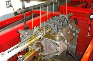
One way to eliminate the effects of gravity on the boring bar is to use a vertical boring machine. Rotating the block and bar 90° so the block and bar are straight up and down provides a truer, straighter cut says one manufacturer of this type of equipment. It also saves floor space because the machine has a smaller footprint.
Another way to circumvent the issue of bar sag is to use a 90° right angle cutter attachment on a milling machine. Instead of using a long steel bar to pass single or multiple cutters through the main bores, the 90° cutter is lowered into the space between each main bore, then moved sideways to machine the bore ID. It’s sort of like working around a corner. With computer numeric controls (CNC), each hole can be precisely machined to exact dimensions and the centerline of each hole perfectly located and aligned with all the rest. This technique works especially well on large, heavy blocks that may be too long for most boring bars.
OHC Applications
When overhead cam cylinder heads came into widespread use, it quickly became apparent that line boring or honing would be needed to correct a variety of problems (cam bore wear, distortion and damage as well as cylinder head warpage). Aluminum heads can be easily warped by overheating. When the head gets hot, it tends to swell the most in the center area. The head bulges up in the middle causing misalignment in the cam bores. This, in turn, can cause uneven wear in the cam bores, camshaft sticking or even cam breakage.
If an OHC cam won’t turn in the head, it means the cam is sticking because either the cam is bent or the head is warped. In the case of a bent cam, the center cam bores will show excessive wear or be worn out of round. If the head is warped (which many aluminum heads are), the head should be straightened BEFORE it is line bored or resurfaced.
Note: Most of the distortion will typically be in the center area of the head. When checking the flatness of the deck, don’t just place your straightedge down the center of the head. Also check flatness over the head bolt holes along both sides of the deck.
To straighten the head, bolt the head to a heavy steel straightening plate using shims under the high spots to offset the warpage. Then place the head in an oven that has been preheated to about 500° F. Leave the head in the oven for about two hours, while monitoring the temperature of the head so it is kept at about 450° to 475° F. Use a contact pyrometer to check head temperature, not an infrared pyrometer. You don’t want to get the head too hot (over 500° F) because this can soften the head too much. Also, if you don’t get the head hot enough (at least 450° F), you may not straighten the head at all! At the end of the oven cycle, pull the head out of the oven and allow it to air cool.
Other methods of straightening aluminum heads include cold pressing the head (risky because you might crack or break the head), TIG welding on the top of the head to pull it flat, and spot heating with a rosebud torch to counter the distortion.
The main goal should be to get the alignment of the cam bores as straight as possible rather than straightening the deck surface. Low spots in the deck can always be built up by welding and machining the head flat (which may require using a head gasket shim depending on how much resurfacing is required). But as a rule, once you get the cam bores straight, most of the distortion on the deck will also disappear.
In the past, a popular fix for OHC heads with worn cam bores was to line bore the head to accept bearing shells or inserts. Nowadays, the more popular fix seems to be cutting the head to accept a cam with oversized journals.
Alignment Checks
The alignment of the crankshaft and camshaft bores in blocks and OHC heads can be checked by placing a straight edge in the bores or along the bore parting lines and using a feeler gauge to check for misalignment.
How much misalignment is too much? It depends on the engine and the application. A light duty passenger car engine is not as critical as a high revving performance engine or a hard-working diesel engine. As a rule, most passenger car and light truck engines call for .002" or less of misalignment between all the bores, and .001" or less misalignment between adjacent main bores. For performance engines, you can reduce these maximum tolerances by half or more.
Another dimension to look at is bore wear. Bore diameters should usually be within .001" of specifications to support the bearings properly, with no more than .001" out-of-roundness if the horizontal dimension is greater than the vertical dimension.
Also check for wear on the thrust bearing surface of the main cap. If worn or damaged, this surface should also be remachined.
Changes In Centerline
When main bores in engine blocks or cam bores in OHC heads with caps are worn excessively, removing the caps, grinding them down and align boring or honing the holes back to size with the caps in place can usually restore the bores. But this will change the centerline of the crankshaft or camshaft slightly, moving it further into the block or head unless corrective measures are taken to prevent this from happening.
If a block is being align honed, the bushings that support the honing bar are usually mounted in the undamaged end journals of the block. Centering pins in the middle of the bar are used to center the bar in the center main bore. Stock removal is usually limited to about .003" or less when honing.
With line boring equipment, pilots are used to position the bar. This allows faster stock removal and does not usually require any oil or lubricant. Changing the position of the bar will change the centerline of the bores and crankshaft.
Many engines can handle a few thousandths variation in the position of the crankshaft centerline but others cannot because of changes it causes in other critical dimensions such as the deck height of the pistons when the crank is at top dead center (which affects compression, piston-to-head clearance and valve-to-piston clearance). Performance engines and diesels are much more sensitive to centerline changes than light duty passenger car engines.
Because main bore alignment is so important, it should be the first thing that is machined on any engine. And it must be done accurately because most of the other critical dimensions center off the crankshaft.
Equipment Review
Line boring and honing equipment is available from various suppliers, and you can spend as much or as little as your budget can afford. Some equipment is dedicated for the sole purpose of line boring and/or honing only (some for engine blocks only, some for OHC heads only, and some for both). Other types of equipment offer multiple capabilities and are full feature multi-purpose machining centers.
At the high end of the spectrum are machines like Rottler’s F67/F68 CNC machining centers with their unique 90 degree right angle drive line boring attachment (which sell for around $70,000 or so depending on the accessories), or their even larger F80/F90 machining centers for handling big diesel engines and industrial engines ($150,000 to $250,000 depending on the size and capabilities). The big F80/F90 machines can handle bore sizes two to seven inches in diameter. Set-up is quick and easy because there is no need to stop and measure bore diameters during the process as is the case with ordinary line boring or honing equipment. The dimensions are programmed in and the bores are then automatically machined to within .0001" to .0002" of specified tolerances. Rottler’s 90 degree right angle boring attachment can also be purchased separately for around $10,000 for use on an existing milling machine.
Sunnen sells three different machines. The "CH-100" is primarily a line honing machine for engine blocks, but accessories include a line boring attachment, cam boring attachment and oil grooving tool (for installing oversize roller cam bearings or enlarging cam grooves for better oil flow). The price is around $11,000. Sunnen also sells the "VAB 3600" Vertical Align Boring machine manufactured by DCM Tech. This is the only machine on the market that line bores vertically. The machine uses a single point fixed cutter and can cycle a block floor-to-floor in as little as 15 minutes. The VAB 3600 can handle most engine blocks as well as OHC heads, and sells for around $16,000. Sunnen’s third machine is a portable align boring system for doing main bores and cam bores in engine blocks made by RMC. This boring system indicates the bore centerline and can be used to move the centerline of the cam or main bores up or down. The price is around $9,000.
BHJ sells a "LBF-1" Line Boring Fixture that fits on a Bridgeport mill for around $8,000. With this type of equipment, you can do main bores and cam bores in most passenger car and light truck engine blocks. BHJ also sells its "CTA1" Cam Tunnel Alignment Fixture for use with other line boring equipment. The fixture helps you establish the location of the boring bar in the block for proper cam alignment.
For $11,000 to $18,000, CWT sells its "LH100" line honing/boring machine that can handle most passenger car and light truck blocks as well many diesel blocks and OHC cylinder heads. The machine has all manual controls and extra heavy construction for added rigidity and strength. The fixturing allows blocks or OHC cylinder heads to be easily and quickly mounted. Variable speed allows the operator to choose a speed that works best with the type of metal and bore diameter. Special custom eccentrics are also available if a user wants to offset the bore centerline.
Peterson Machine Tool has two machines, a "BT6" line boring machine (base price $18,000) for cylinder heads and blocks up to 32 inches in length, and a "BC4" boring machine that can handle larger blocks (like diesels) up to 63 inches in length ($35,000).
Winona Van Norman sells an "LB3200/3800" dedicated line boring machine that can do most passenger car and light truck blocks or OHC heads for $25,450, and larger Italian-made line boring equipment for large diesel and industrial engines.
For a small shop who may only need a simple line boring bar for cutting OHC cylinder heads, Silver Seal’s "QV1001" Quick Bore Line Boring package sells for $3,600. Various cutter sizes are available (cutters for the top 10 heads cover about 80 percent of the OHC market), including ones for boring Harley Davidson motorcycle engine cases.