With photos and words by Steve Temple
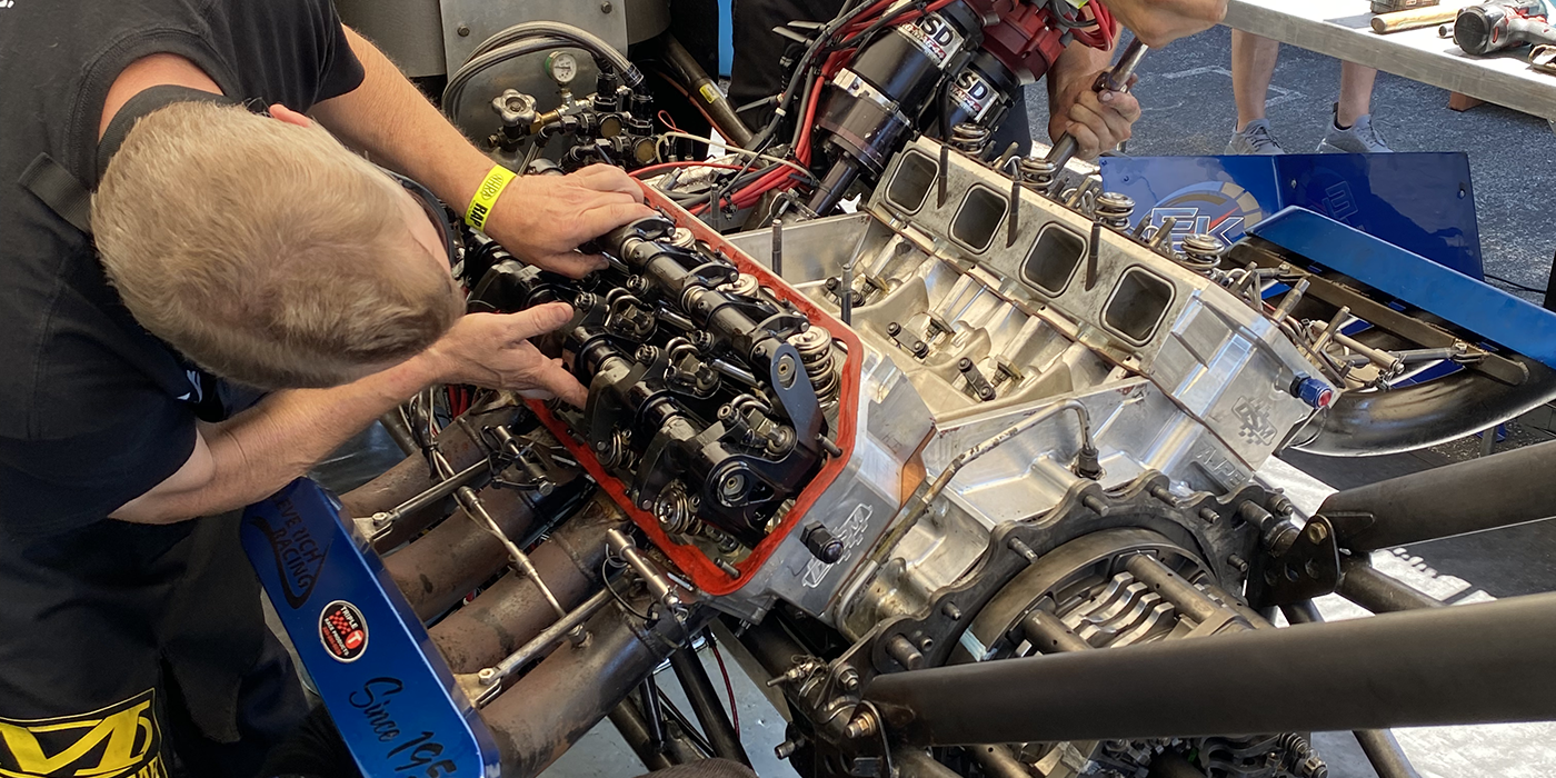
As any experienced engine builder already knows, a drag race engine is made up of hundreds of precision parts bolted together to form an assembly that spins at a furious rate in order to propel its vehicle to victory. Meeting this challenge requires that all those parts going into this assembly be just right. Because the entire engine assembly is such a large and diverse topic we won’t be so pretentious as to try to cover it in its entirety, so we’ll focus on the heart of the matter, the crankshaft. Not just any common crankshaft, but more specifically shafts used in the sport of drag racing when the capacities of the stock shaft are far exceeded.
By simple definition the object in question is a shaft with U-shaped cranks. Its sole purpose is to convert the up-and-down motion of the pistons into a rotary motion that will eventually turn the rear wheels.
The differences between a stock shaft and a racing piece are many. These provide a multitude of benefits that make a specialty shaft highly desirable: it’s stronger, more precisely machined, has greatly improved oil control and is available in a limitless variety of configurations. It will also lessen the likelihood of taking a perfectly good assembly made up of expensive performance parts and turning them into a 9,000rpm hand grenade.
Before we get into specifics of crankshaft technology, it’s important for engine builders to identify what the customer’s expectations are. The engine builder should consider how long the end user intends to keep a car with the engine intact.
For instance, some people jockey a dragster in different classes, while other people may stay in a particular class for a long time. Someone else may have the goal in mind to start out in a Pro category and then go to Super Pro, and then maybe from there they want to go to a Quick 16 if you’re talking bracket racing categories.
One of the biggest problems you can run into is a customer making a decision based solely on dollars. The problem is, what’s the cost per year, or per lap to go out and run these things? An engine builder can get caught in this price trap, unless he can convince the customer to spend a little more money up front so that in the long run the cost of ownership isn’t so great.
So what makes a good racing crankshaft? First on our list is the type of metal used. In the case of high-end racing crankshafts the choice is typically between forged steel or billet steel. The grade of that material will differ by manufacturer to best suit the needs of their specific design. As with all selections you will find supporters from both sides and in equal numbers, but there are a couple of points that we all can agree on.
Because a racing crank must survive extreme torsional loads as well as bending and flexing that would bring lesser material to its knees, strength is paramount. A performance crank has to be tough to survive the rigors of racing.
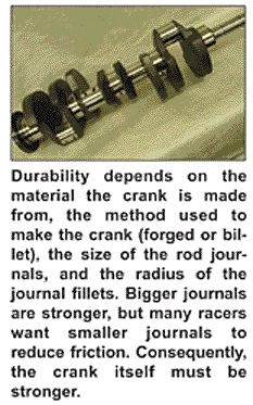
Durability depends on the material the crank is made from, the method used to make the crank (forged or billet), the size of the rod journals, and the radius of the journal fillets. Bigger journals are stronger, but many racers want smaller journals to reduce friction. Consequently, the crank itself must be stronger.
While you might be under the impression that steel is steel is steel, the materials used in a crankshaft are critical. A 1053 high-carbon alloy steel typically has around 100,000 psi tensile strength which is perfectly adequate for a stock or even mild performance engine, but is not strong enough to withstand the rigors of serious racing. Stock cast cranks can safely handle up to 350 horsepower in a small block V8, or up to 400 horsepower in a big block V8 with a redline of 5,000 to 5,500 rpm. Get past this and you’ll wish you had a better, stronger crankshaft.
A forged crankshaft made of 5140 grade steel alloy is a good upgrade and has around 115,000 psi tensile strength. A 5140 alloy contains less carbon (0.38 to 0.43 percent) than 1053 alloy (0.47 to 0.55 percent), plus it has chrome (0.9 to 1.7 percent) and silicon (0.2 to 0.35 percent) to improve durability. The difference in carbon between 1053 and 5140 is not as important as the chrome, which add strength and toughness. With the proper heat treating, a 5140 forged crank is an economical choice for many Sportsman class racers or the street/strip Saturday night racer.
If you’re building a small block V8 that’s capable of making more than 450 horsepower, a big block that’s making upwards of 550 horsepower or you’re pushing the engine’s redline beyond 7,000 rpm, you should upgrade to a performance crank – which usually means a forged or billet 4340 steel crank. Forged cranks made of 4340 alloy typically have a tensile strength of 140,000 to 145,000 psi and are much more resistant to fatigue than 5140 or 1053. A forged 4340 billet crank will typically have a fatigue strength of 160,000 to 165,000 psi. The increased strength is due to the addition of nickel (1.65 to 2.0 percent) and molybdenum (0.2 to 0.3 percent).
However, the ASM (American Society for Metals) grading standards allow a certain range for the amount of each element in the steel so not all “4340” alloys are the same.. If the concentration of a particular element – chrome, nickel or molybdenum, for example – is extremely high or low it can affect the ultimate strength of the alloy. We’ve heard reports that some 4340 alloys from offshore suppliers don’t necessarily conform to ASM standards. Some may contain contaminants that can have an adverse effect on strength and other properties. That’s one reason why some offshore forgings are priced much less than their domestic counterparts. The alloys are not the same.
The strength of the crank not only depends on the base alloy, therefore, but also on how it was made (whether it was drop-forged or machined from solid chunk of billet steel). A welded up stroker crank may be okay for a street engine but probably isn’t strong enough for racing.
Forgings generally produce a flowed grain structure, which is stronger than a casting. Even so, the forging process stretches, pulls and deforms the grain structure, and subsequent machining cuts through the grain structure. The strength of the forging also depends on the metallurgy of the alloy used, and the heat treatment that is applied to it after it has been shaped. Forgings require a die to shape the metal. Dies and forging presses are expensive (which adds to the cost of the crankshaft), so the availability of forgings for various applications depends on their popularity and how much people are willing to pay for a forged crank.
Billet crankshafts, by comparison, are CNC machined from a solid chunk of forged steel. The grain structure is not stretched or deformed, and machining leaves fewer residual stresses in the metal. Consequently, some crank manufacturers say billet cranks are the strongest cranks available. Most Top Fuel drag racers run billet cranks, as do many circle track racers. Another advantage with billet cranks is that CNC machining allows a crank to be custom made with virtually any stroke, journal diameter, configuration or countershaft placement that will fit the engine. A billet crank can be one-of-a-kind or mass produced.
Most racing cranks are heat treated and case hardened to provide additional strength and durability. The journal surfaces may be hard chromed, nitrided or induction hardened.
Nitriding is often used, and can be done by several methods. Some crank manufacturers use a “plasma nitriding” process that vacuum-deposits ionized nitrogen on the surface of the crank inside a high temperature oven. Others use a process called Tufftriding that soaks the crank in a hot “ferric nitrocarburizing” salt bath, or heats the crank to 950° F in an oven filled with nitrogen. Nitrogen penetrates the surface of the metal and changes the microstructure of the steel. This roughly doubles the hardness of the surface from about 30 to 35 Rockwell C to 60 Rockwell C, and increases fatigue life up to 25 percent or more.
Of course strength is not limited to what the base metal alone can deliver. Surface coatings like nitriding and nitrocarburizing can increase the surface hardening to any number necessary. And there are coatings that will repel oil from the non-machined surfaces to help improve the crank’s ability to move through the air with the least amount of parasitic drag.
Another choice that is seeing more use is cryogenic processing where ultra-low temperatures are used to alter the state of the metal. The real advantage is that this is not a surface-only process so further machining will not eliminate the beneficial effects.
Another area of the crank that receives a lot of attention is the un-machined surface of forged cranks. To take another step closer to perfection with a forging the un-machined surface can be polished to remove the stress risers from its surface. Then those same surfaces can be shotpeened to form a tough skin over the surface that increases its fatigue resistance.
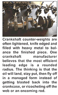
As we all know, the counter-balance weights get a lot of attention. They are lightened, knife edged and filled with heavy metal to balance the finished piece. The reasons for all this attention are basic: to make the crankshaft revolve in the contaminated atmosphere of the crankcase with as little resistance and/or vibration as possible. Although knife edging is the most common way to streamline the counterbalance there are other methods.
One leading crankshaft manufacturer believes that the most efficient leading edge was a rounded radius.”
It makes sense if you think that the crank flange is like a snowplow. When the plow goes zipping down the road with the blade at an angle, it throws material off the side. But if you took the same blade and put it square to the front of the vehicle it would build up a big pile in front of it then gradually snow would start rolling off the side and right down along the side of the vehicle, so it wouldn’t splatter or fly all over the place.
“You want the stuff to land, stay put, then fly off in a managed form instead of getting blasted back into the crankcase, or ricocheting off the web or an oncoming rod,” says the company spokesperson.
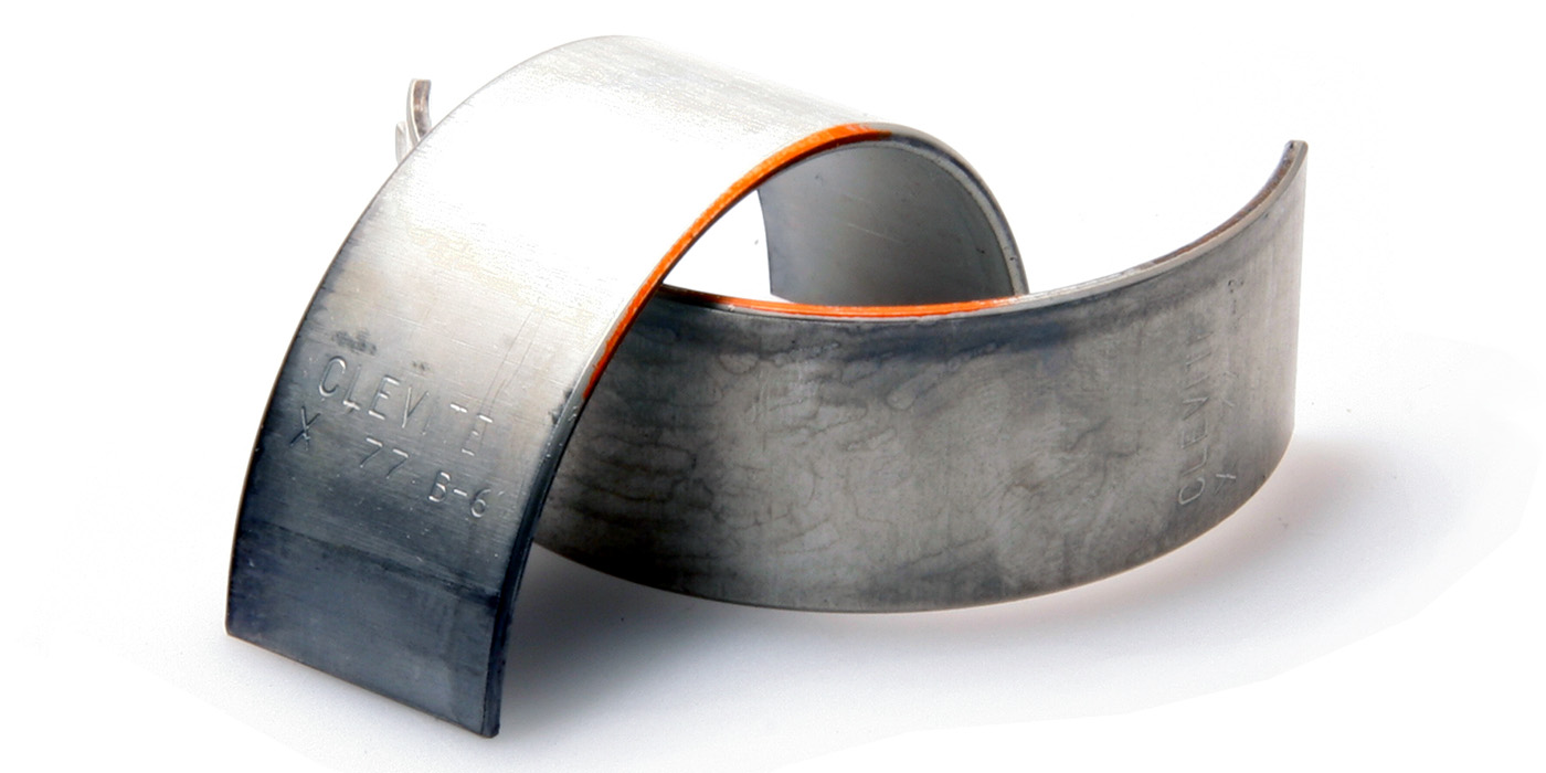
Whatever type of bearing you choose, experienced drag-racing engine builders like Jim VanGordon of VanGordon Racing makes sure to deburr the corner of the thrust bearing in the center of the block to remove any of what he calls dingleberries or stalagtites. “Otherwise the thrust bearing might not seat properly, and cause wear,” he noted.
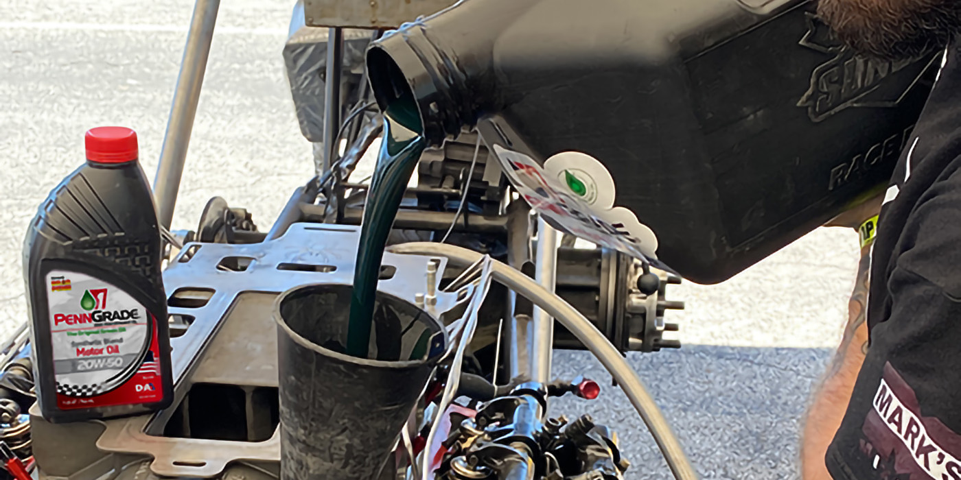
VanGordon also uses full-groove industrial bearings with channels on both the top and bottom, to ensure plenty of oil. And before installing the crankshaft, he applies engine oil to all the bearing surfaces. He won’t use white lithium grease, because he feels it can clog the filter.
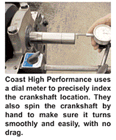
Here’s one more simple but really essential step: set the thrust bearing by tapping gently on each end of the crankshaft. He then checks endplay with a pair of screwdrivers and dial indicator -.006″ is ideal. He also spins the crankshaft by hand to make sure it turns smoothly and easily, with no drag.
Looking at crankshaft technology in general, as with everything in life there are several different paths that lead to the end of the road; the scenery is different along the way, but they all end up the same place. Well, the crankshaft situation seems to be the same, there are different materials, different hardening processes and differing ideas on crankshaft technology but in the end they all seem to turn out a very reliable, durable product.
As one maker of performance crankshafts summed up, “We see fewer crankshafts broken today than we did ten years ago.” That’s quite a feat when you stop to think about it. This is a time when engine builders commonly build larger displacement, higher revving engines that crank out more horsepower and build more torque than ever before, yet there are fewer failures. Which is good news for both engine builders and their customers.
BEYOND THE SHINE
By Ken Barton
Micropolishing has evolved rapidly over the past 30 years and now is understood as a controlled metal removal, surface finishing process. Micropolishing has the ability to enhance bearing characteristics such as roundness, flatness, and reduced lobing, all of which improve the micropolished product’s performance and durability.
Typical metal removal during micropolishing is between .0001″ – .0002″ with a maximum generally not exceeding .0004″. With this small amount of material to work with, the bearing surface and geometry must be in this range to allow the micropolishing process enough material to improve the characteristics described above without going below the minimum size tolerance.
Because engine bearing specifications have become tighter to improve engine efficiency, i.e., mileage, durability and performance, the dimensional tolerance, weight and mating surface of a component’s surface also requires further enhancement.
To achieve these required higher quality surface finishes, micropolishing uses a non-compressible abrasive film with a closely graded abrasive crystal in place of the traditional paper or cloth backed abrasives. This non-compressible, closely graded abrasive crystal composition is used in conjunction with a film backing made of a hard and uniform material to support the abrasive film.
With the abrasive film backing or shoe designed to conform dimensionally to each particular diameter and length of the bearing surface, it allows the perfect form of the manufactured shoe. In combination with the non compressible abrasive film we can now generate the improved characteristic’s onto the bearing itself.
Using the materials and process consistency described, the micropolishing process has proven itself to be a significant improvement over chemical, electrostatic, slurry and belt polishing processes.
There have been many names used over the years for describing the surface finishing process. These include: lapping, OD honing, polishing, superfinishing, microfinishing, and micropolishing. Most of these descriptive terms are still in use today. However, although they are often used and understood to be describing the same process, they are each in their own way unique.
Other enhancements besides improvements to geometry and surface finish that can be accomplished using the micropolishing process include: controlled cross-hatch, straight line, tangential fillet radius blend, ferrite cap removal, and in some cases, gauging is also added to this process for sizing.

