Q: We’ve had complaints of recurring oil leaks around the cylinder head on some Cummins diesel engines. Any suggestions?
A: The AERA Technical Committee offers the following information regarding revised studded cylinder head bolts for Cummins 10.0L and 11.0L, L10 and M11 diesel engines. This information should be used any time cylinder head work is performed. These studded bolts are the smaller 10 mm bolts used on the fuel rail side of the cylinder head.
On occasion, some OEMs find it necessary to remove and install one or more of the fuel rail side cylinder head mounting cap screws to facilitate the mounting of assorted brackets or clips to the engine. When the cap screws are again installed, improper installation practices have occasionally resulted in oil leaks at either the cap screw or the gasket joints.
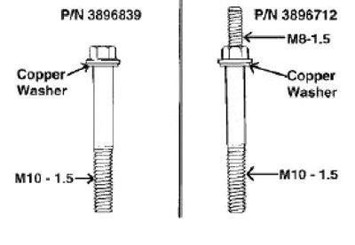
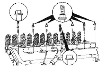
Two cap screws (p/n 3896712 and p/n 3896839) have been released for use with L10 and M11 engines. Cap screw p/n 3896712 is a studded cap screw (M10-1.50) with M8 threads on top. The studded cap screws will provide an installation point for assorted brackets and clips used by OEMs without disturbing the original installation of the cap screws. The studded cap screw is used in five of the seven cap screw locations on the fuel pump side of the cylinder head mounting. The other two locations are not used as studded cap screw installation points due to interference with the air compressor air inlet tube and other hardware, such as bus alternators and Freon compressors. Cap screw, p/n 3896839, is a hex head cap screw. This cap screw is a (M10-1.50 x 75) and is used in the other two mounting locations on the fuel pump side of the cylinder head mounting. This cap screw supersedes cap screw p/n 3028272, which is a twelve point cap screw. Refer to Figures 1 and 2.
The five factory installation locations of studded hex head cap screw, p/n 3896712, are the more often used locations for the mounting of assorted brackets and clips. However, the studded cap screw can be mounted in the front location if some other piece of hardware used by different OEMs does not interfere with its use. Follow the installation procedure given below to install the cap screws.
1) When installing cap screw, p/n 3896839, and p/n 3896712, copper washer, p/n 3882885, must also be used.
2) Torque studded cap screws to 35 ft.lbs (47 Nm).
Q: We seem to have crank related engine vibrations and other problems on some Ford 6.0L engines after we have re-installed the crankshaft. Any help?
A: The AERA Technical Committee offers the following information regarding crankshaft removal for 2003-2007 Ford 6.0L VIN P diesel engines. This information should be considered any time service work is related to the crankshaft, including clutch and transmission work.
This engine uses additional components for the crankshaft assembly. Those components are; a flywheel front adapter, located between the flywheel/flexplate and crankshaft as well as a separate bolt-on rear flange. The rear flange should never be removed from the crankshaft. This rear flanged is secured to the crankshaft by six mounting bolts and also provides a concentric rear main seal surface for the seal. If the flange is removed, the orientation will be upset and re-establishing it correctly may not be possible by simply bolting it up.
An incorrectly installed rear flange piece will be off the center-line of the crankshaft, which will increase flywheel round out and cause engine vibration. Other complications may include oil leakage, seal damage and possible transmission front bushing wear.
The rear flange is part of the crankshaft manufacturing process and not intended for service replacement.