It never occurred to me to even ASK whether the cam I recently had re-ground for a Buick Nailhead engine was ground with flat or tapered lobes. Like a great many others, I’d forgotten that some vintage engines had flat lobe surfaces because I’d gotten so used to everything having tapered lobes. This, unfortunately, can mean that if you have the wrong combination your cam will often not survive break-in and will certainly not last as long as it should.
My old friend Gary Cross brought the subject up when I mentioned I was building the Nailhead. As a former tech guru at Melling, he had to make sure these parts were compatible and the differences between flat and tapered cams and flat or radiused lifters became a critical issue in his job. He’s also a Nailhead fan and so ran into the subject when he had his last Nailhead cam ground. Anyway, he got me started on some research that soon became surprisingly informative and that can have serious importance to anyone building a vintage engine.
I then went to several of my other friends in the aftermarket (including engine builders, cam grinders and marketing and technical experts at some of the industry’s leading suppliers … see the end of this article for a list of my sources and a listing of other suppliers who can answer your questions) for information. We went as far as digging up original product blueprints and verifying current lifter specs. We also looked at current replacement part specs and learned that in one or two cases there were some aftermarket parts that missed this flat vs. tapered issue and were incorrect.
I have to say it focused some attention on the issue and got everyone to double-check and verify they had the right stuff. To me that’s a sign of responsible, quality parts sources – when they constantly update, upgrade, and quality control instead of making do with whatever they happen to have. Anyway, this all gets a little complex, but let’s give it a try so you can wrap your brain around what we are dealing with.
First we have to define the terms a bit. What is called a flat lobe cam is one where the surface of the cam lobe is parallel to the centerline of the cam. A tapered lobe cam is designed where the surface of the cam lobes are ground at an angle to the centerline of the cam – usually between .0015? and .0030? change on a lobe side to side.
For lifters, a flat lifter is one where the bottom surface of the lifter is perpendicular to the centerline of the lifter. In addition, the radius of the bottom surface is about .160?. That means lifter bottoms have the same radius as a sphere with a radius of .160? (or a diameter of .320?). This translates out to a difference between the center point
in the lifter bottom and outer edge of no more than about .0005?. On the other hand, a crowned lifter will have a radius of .037?-.060? (.074-.120? diameter) and this translates to between .0010? and .0030? difference between center point and outer edge. A Nailhead flat lifter has a spec of .00025? +/- .00025? whereas a similar crowned lifter often misused in its place has a crown spec of .0011? +/- .0003.?
The way this is checked at the manufacturer is with a gauge somewhat like a bridge gauge. It has two stops at .750? apart and a center dial gauge pin, so when it is set on the lifter face it will show the deflection between the center point on the lifter face and those two points toward the outer edges. Again, a Nailhead flat lifter has a spec of .00025? +/- .00025? whereas a similar crowned lifter often misused in its place has a crown spec of .0011? +/- .0003? using this standard of measurement.
Then we have to look at lifter rotation. Getting lifters to rotate means that instead of flat-spotting one portion of the lifter, the wear that occurs happens more gradually and extends the life of the cam and lifters. It also means that instead of the cam just scrubbing against the lifter, the lifter rotates as it moves over the cam and reduces friction.
Finally, rotation and its effect on wear means that a specific amount of contact area is maintained between cam and lifter that spreads the impact energy over a large enough area to withstand the pressures but not so much that it increases friction.
The original technique for getting rotation was to offset the lifter relative to the cam lobe center. That positioned the lifter so more of one side was in contact with the cam than the other, and that created a tendency for the lifter to rotate. Within the limits of the cam and lifter surfaces, the more you offset the cam the more rotation you get. The first flat lobe cams used this offset exclusively to create the rotation.
At some point engineers determined that they could get good rotation and improve cam thrust if they went to a tapered cam. By tapering the lobes, they could determine which way the cam wanted to thrust as a result of both distributor gear and timing gear rotations. Generally if you can get the cam to be almost neutral, the cam thrust surfaces on the block or cam plates wear less and cam gears wear less. Many times the thrust controlled by cam taper is set up so the cam JUST wants to move to the rear of the block but with low energy.
Chevy cams are tapered so all lobes thrust to the rear, but use less lifter offset to reduce the amount of total thrust – as a means to compensate for all lobes pushing in the same direction. Fords used cams with half tapered one way and half the other way. Each engine is designed using all these things to get an acceptable thrust level and lifter rotation at the same time.
The notable exception was the Nailhead. When designed, the Chief Engine Designer at Buick was a fellow by the name of Joe Turlay. Joe was convinced (and I see some logic to this) that if you properly designed the valvetrain you could create a relatively neutral cam thrust condition that would not require either a tapered cam or even a thrust plate.
Given that the Nailheads show nothing for thrust wear on the block face even at this late date and no tendency for other valvetrain failures, I’d say he was probably right. While unable to pick his brain on this, I think the combination of a flat cam lobe, the correct amount of lifter bore offset, and the oiling at the cam gear/block face that would create a sort of hydraulic thrust against the action of the distributor/oil pump drag to the rear created this neutral thrust and a durable engine.
As a side note, the 215 aluminum engine was designed during his tenure and he was over-ridden on this design for it. I believe that this was because of the concern that the aluminum block would not be durable enough to last as a thrust surface against the cam gear. Remember that not a lot was known about how aluminum would survive in that era. When the next generation of Buick engines was designed, Joe was retired and the new engineers moved to the more conventional tapered cam scenario.
The problem with all this is that you can’t just arbitrarily alter the cam lobe type without other problems cropping up. For example, if you started with a flat cam and put tapered lobes on it, you might well find that instead of the balance front to rear you get a big thrust in one direction or the other. Often, this is resolved by having some lobes taper to the front and others taper to the rear (often bank by bank), but it doesn’t always work out. That means that if your engine originally had flat lobes you will probably be best served if you use the flat lobe cam. The same goes for the tapered cams – you don’t want to use a flat lobe cam in a tapered application and for the same reasons.
Worse yet are the lifter issues.
If you try to use a flat lifter on a tapered cam the high edge of the cam lobe is the only contact between the cam and lifter, creating a very high pressure contact area and rapid wear and failures. If you try to use a crowned lifter on a flat cam, the contact area is again concentrated at the center of the lifter and proper lifter rotation cannot occur. Again rapid wear is the result. While the flat cam and crowned lifter is the lesser of two evils, it will reduce engine life at the very least and can cause rapid failures.
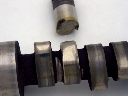
How do you tell what you have? Let’s look at the cams first. Ideally, you will be able to ask your cam grinder or supplier and they will know. Most often this works. However, I have found that there are some that do not know and will just guess. Not good. So what you can do is grab a caliper or micrometer and check. A tapered cam will, obviously, be taller on one side of the lobe than the other. What makes this tricky is that you must make sure you are measuring at the exact same location on either side or the change in lobe will skew your measurements. If you can get a caliper on the lobe, you’ll see that the flat jaws of the tool will rest on one side and not the other.
Alternatively, you can lay the cam on a perfectly flat surface and you should be able to both see and measure (with a feeler gauge) that the one side of each lobe is shorter than the other side. This measurement will be about .0002? across a distance of .300? of lobe width or between .0015? and .0030? from side to side. You’ll need to chuck it in a lathe and use a dial gauge to check this accurately.
Lifters can also be measured. If really flat, if you place a pair of them end to end you will see that they either do not rock against each other or do so VERY little. If crowned, they will rock significantly. You can get the same kind of effect if you place the business end of the lifter on a perfectly flat surface. You will find that a .0008? feeler gauge will not fit under the outer edge of a flat lifter but that it will on a crowned lifter. The flat lifter will have as much as .0005? but the crowned lifter will have between .0008? and .0015?. This can be a little tricky to measure because the lifter must be squared in the caliper so the caliper is resting flat on the center of the lifter face and not cocked to either side.
Maybe by now you’ve started to consider the effect of all this. In a day when we have ZDDP levels dropping in oils, leaving a lot of flat tappet cams vulnerable to excessive wear and failures, we also have the wrong lifters being sold. The example I’m using is the J-896 lifter for the 1957-’66 Nailhead Buicks. This engine has a flat lobe cam with flat lifters as I mentioned before and confirmed with Dennis Manners, another Buick engineer and noted Nailhead guru. The taper is in the .160? radius range, meaning the lifter face will show between zero and .0005? of taper.
Some companies are selling the J-846 lifter, originally designed for the 1957-’69 Cadillac engines in its place. The J-846 lifter has a .035? radius and is not compatible with the flat Buick cams, creating excessive wear. In addition, the J-896 lifter has an outside diameter of between .8418? and .8423?, where the J-846 is larger at .8420? to .8427?. In most cases this diameter will not make a difference, but if not checked you might find that they could stick in the lifter bore.
There are some who have decided to consolidate the J-896 into the J-846 and simply eliminate the J-896 lifter from production. Yes, it is cheaper. Yes, for mild engines and low miles a good many of those lifter/cam combinations will survive long enough so the real source of failure is hidden. In many cases this combination just means that the engine will have a shorter life and you may get by.
However, if you are building a performance engine or plan long miles or heavy use, the couple bucks difference to get the right lifter for the cam and get it made of quality materials makes a lot of sense. If you want a personal recommendation, I like Johnson/HyLift lifters, made in the U.S., made to original specs, and made with the correct alloys.
In some cases, offshore makers have been altering the composition of the lifter body material, sporadically reducing the molybdenum and nickel content – I’m told because it costs more and there are material shortages. The lifters still being made in the U.S. have a standard for materials that is much higher.
You won’t see the same lifter/cam failures as with imports that have been tested for a 36,000 mile lifetime and are recommended ONLY for bone-stock OEM applications and not for high performance, heavy duty, high mileage, high lift, long duration, high spring pressure, or other non-stock applications.
There are a couple of companies that went with both a tapered grind on their cams AND the crowned lifters to match. If the cams are properly ground, meaning that the balance of tapers either front-to-rear or rear-to-front recreates the relatively neutral condition of the original flat cam flat lifter configuration, this should be acceptable.
I’d say that a quality grinder, armed with the required data and a detailed knowledge of both the cam and the engine, should be able to provide a cam and lifters that should live. I’ve spoken with Mike at T.A. Performance – a well-known quality Nailhead Buick builder – and he tells me that they’ve done just this. He also tells me that he has not had any failures from this as well, and Mike’s not a BS-er.
My only question would be why you’d want to reinvent the wheel – especially if it ain’t broke – and that’s pretty much the position that my cam grinder takes. In my talks with him about this issue he made it clear that he grinds all his cams as per the factory design and supplies the flat lifters to accommodate them. By doing this, he feels that he bypasses the potential problems with mismatches or alterations changing thrust or wear issues and finds no limitations on the performance aspect of his products. If it ain’t broke, don’t fix it.
The NEW cam he did for the Nailhead project started with a new cam blank and grind options were wide open, but he chose to grind the cam with flat lobes as per OEM and the new Topline/Hy-Lift Johnson lifters are a match to it – nothing to worry about.
Mike made another good point in suggesting that the quite low spring pressures you find in most Nailhead builds means that valvetrain components don’t often fail. With on the seat pressures of 60 to 85 lbs. and open pressures of 150 to 200 lbs., the friction-based wear issues diminish. This is why some who have put crowned lifters on flat lobe cams have seen their engines live. While the adverse condition remains, it just takes longer to see the effect of mis-matched cams and lifters than on another engine with much higher spring pressures.
So what does this mean to the practical builder? First off, make sure you know what you have and instead of buying on the basis of “cheapest wins,” look for quality. That doesn’t mean you should throw money around, but it does suggest that you buy from reliable sources who know what they are selling and don’t have to guess. Get a matched set.
That means that you either want the correct OEM replacement parts or the altered parts must take into consideration unintended consequences of those changes. With this in mind, you should then see that by knowing this issue exists and the reasons behind it, and knowing what the choices and concerns are, you should be able to get the right parts that will serve you well.