The
1998-2002 Honda Passport (3.2L) V6 engine has a “non-interference”
design. This means the valves never contact the pistons, even when the
valves or camshafts are not correctly timed, or even if a valve is
fully open and its piston is at top dead center (TDC).
• The ratio between the camshaft drive gear and the camshaft gears is
1.33 to 1. This means the timing dots on a correctly timed camshaft
will only align with the dots on the camshaft drive gears every 4th
turn of the camshaft pulley.
• The left and right intake camshafts are different. On the cam lobe
side of the camshaft gear, the left intake camshaft is marked “LI,” and
it has dual timing dots; the right intake camshaft is marked “RI,” and
it has a single timing dot.
• The left and right exhaust camshafts are the same. On the cam lobe
side of the camshaft gear, both camshafts are marked “LE” and “RE,” and
both have dual timing dots and a single dot.
• Service manual page references are to the 2002 Passport Service Manual.
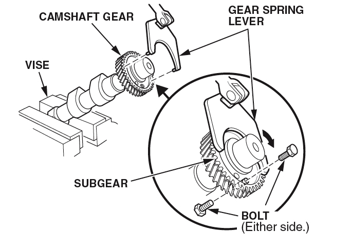
1) Before you install the camshafts, preload the subgears (preloading must be done whenever you remove the bearing caps from a camshaft), Figure 1:
• Make sure the spring is installed between the camshaft gear and the subgear.
• With the camshaft held in a soft-jawed vise, attach the gear spring
lever (P/N J-42686) to the subgear, then turn the subgear until its
threaded hole lines up with the hole in the camshaft gear.
• Lock the subgear to the camshaft gear with a 5 x 0.8 mm bolt through either side of the gear hole.
• Preload the subgears on the other camshafts.
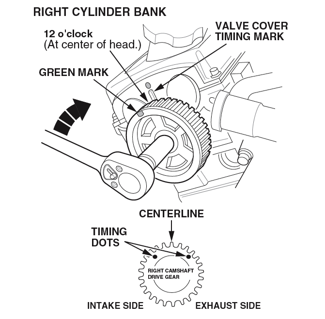
2. On the right cylinder bank, turn the camshaft pulley until its green
mark is at 12 o’clock in relation to the head surface, at the center of
the head. Turning the pulley brings the timing dots on the camshaft
drive gear into their correct position: to the left and right of the
gear’s centerline (Figure 2).
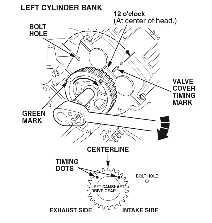
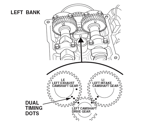
3. On the left cylinder bank, turn the camshaft pulley until its green
mark is at 12 o’clock in relation to the head surface, at the center of
the head. Then turn the pulley counterclockwise until its green mark
points close to the timing belt cover bolt hole. Turning the pulley
brings the timing dots on the camshaft drive gear into their correct
position: to the left and right of the gear’s centerline (Figure 3).
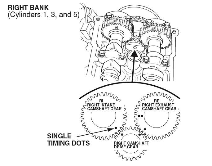
4. Install the intake and exhaust camshafts in the right cylinder bank:
• Set the camshaft marked “RI” into the intake side of the head. Make
sure the single timing dot on the camshaft gear aligns with the timing
dot on the camshaft drive gear.
• Set the camshaft marked “RE” and “LE,” into the exhaust side of the
cylinder bank, with “RE” at the 12 o’clock position. Make sure the
single timing dot on the camshaft gear aligns with the timing dot on
the camshaft drive gear (Figure 4).
5. Install the left cylinder bank intake and exhaust
camshafts:
• Set the camshaft marked “LI” into the intake side of the head. Make
sure the dual timing dots on the camshaft gear align with the timing
dot on the camshaft drive gear.
• Set the camshaft marked “LE” and “RE,” into the exhaust side of the
cylinder bank, with “LE” at the 12 o’clock position. Make sure the dual
timing dots on the camshaft gear align with the timing dot on the
camshaft drive gear (Figure 5).
6. Install the camshaft bearing caps in the same locations and directions they were before you removed them.
NOTE: On the right cylinder bank, the directional arrows on the bearing
caps should point towards the front of the engine. On the left bank,
the arrows should point towards the rear of the engine.
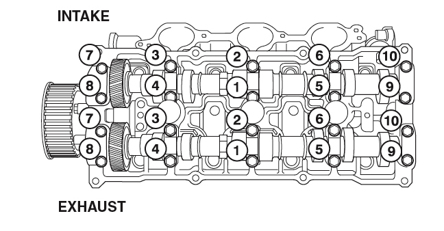
7. Install the bearing cap bolts, then torque them to 10 N.m (7 lb-ft) in the sequence shown in Figure 6.
8. Remove the bolts used to hold the preload of the camshaft subgears.
9. If not already done, inspect the camshaft thrust clearances (refer
to service manual). If any clearances are not within specification,
replace the cylinder head(s).
Some or all of this information was provided by the Automotive
Parts Remanufacturers Association (APRA). For more information on
technical bulletins available through APRA call 703-968-2772 or visit www.AutoBulletins.com.