Mark Dodge, owner of Midwest Cylinder Head, can pinch a penny thin enough to see through (and maybe that keeps his businesses alive and well in poor economic times), so you can bet his choice was thoroughly researched and thought out.
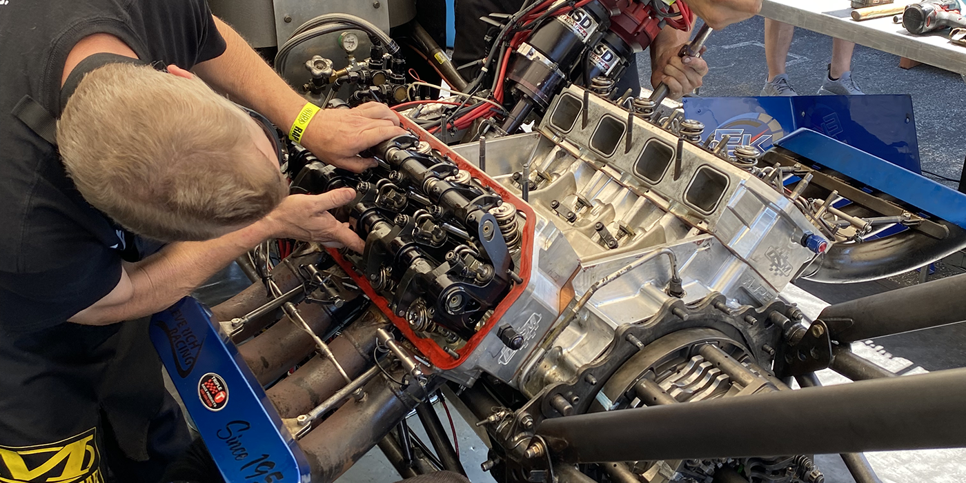
I wanted to see what this unit was all about and so arranged to do some work (lifter bushings) on a vintage engine block – a 400 Mopar big block. These days, with all the insane scrappage going on, vintage engine blocks are getting harder to find and more expensive. At the same time, this old iron isn’t getting any better with age. Finally, when a customer wants to build a performance vintage engine they are spending a hefty wad of cash and expect some precision work for the money.
This 400 block needed bushings to correct for wear and to prevent an oiling issue that a large-lift (over .700?) roller cam experiences at high rpms in some applications. Specifically, the top of the lifter bores get too close to the oil annulus at max lift, oil bleeds off through the top, and this starves the bottom end. Mopar made the whole thing worse by putting about a .100? chamfer on the top. So the solution was to eliminate this chamfer and raise the bushings up about .100? more. This just about doubles oil crank bearing oil pressure according to field experience.
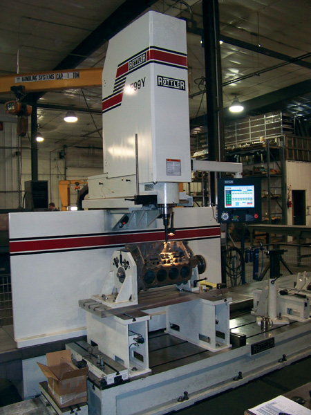
As the block was set up in Midwest’s Rottler F99Y, Gene Frerk and I saw almost immediately that there was lots of wear (.007? top inboard and .0077? bottom outboard on the first exhaust bore) on even this virgin and relatively well-treated block. This was possible to discern so accurately because the block is set up on a support bar that is swept with a probe in two dimensions to get a perfect crank centerline to work from. In addition, the fixture that holds the block rotation is designed so the cam and offset bushings (to fix lifter bore angle) is extremely precise. Finally, we had specs to identify the exact center location of each lifter bore both side-to-side and for spacing front-to-rear.
Each and every bore can be checked using an automatic centerline probe that touches four points 90 degrees apart at each vertical level to identify and record the exact existing centerlines and compares them with the blueprint dimensions. The original machine work on this block varied by as much as .012? in location of the bore centers front-to-rear and by as much as .008? side-to-side. For those who are into high-end performance, this can mean significant variations in cam functions between cylinders and loss of power. It also reduces durability of both cam and lifters.
Once the first lifter bore is located as a distance back from the front thrust surface of the block, it is also located according to the cam bearing bore centers. This means that each and every one of the new bores will be made along a perfect centerline parallel to the cam and at the correct angle relative to the cam. By knowing that each set of bores for a given cylinder are 1.800? apart, that each pair of cylinders at the ends are 3.200? apart, and that the center pair of cylinders are 2.800? apart, this precisely locates each bore. And it does it not by reproducing the inaccurate OEM machine work, but independent of it.
Gene had not done a 400 block with this machine yet, and so spent some extra time making certain that all the calculations and all the dimensions were dead on and recorded in a file in the CNC’s computer. This will allow the next 400 done to be set up much faster and with much higher confidence because the program duplicates each and every bore location within a couple of ten-thousandths over and over every time. Think on that: Once you have the specs you want, this machine will be able to flawlessly reproduce them without any possibility of human error involved.
The finished size of the bores was set so the bushings would have enough press fit (.0025?) to suit the bushing manufacturer. It was interesting to note that while this went on, the CNC would punch every bore in a bank one by one without any further input or need to baby-sit it. Only the boring bar had to be reset in stages – leaving Gene time to get additional work done elsewhere and increasing his productivity.
You’ll note that instead of drilling the bushings after installed or even drilling them prior to installation, these were given a horizontal slot. This engine was converted to push-rod oiling as part of a reconfiguration of the valve train for extreme drag racing use. In such modifications, it is important to significantly limit oil flow to the top end or you’ll starve the bottom and spin bearings. This slot concept allows the oil feed hole in the roller lifter only a short window for oil to flow, cutting down total volume. Later, the builder/customer may alter this but it can be done by drilling to enlarge the opening as required – so it’s a small operation.
Another reason for this was that with a .700?-plus lift cam there is limited depth for the lifter in the bore and limited surface for support. You want the maximum amount of support for the lifters to travel without cocking or encountering excess wear. So this thin slot results in significantly less reduction of the bushing surface than if a conventional large-diameter drill was run through the oil galley to create notches in the bushings that are anything like the OEM configuration. Because the galleys are offset to the side of the lifter bores, you still get good oil flow around them.
While the block was in the machine, it was also decked. In this case the customer wanted the minimum cut required to get both sides the same and squared with the crank centerline and at 90° apart. Align boring could also have been done (this was done in the customer’s own shop so was not needed) as could piston bores. The point is that CNC machines are designed so you can install the block and do all the cutting required in a series of operations without removing it from the setup. This gives a whole new and more precision definition to blueprinting.
The lifter bores did not require reaming or boring after installation. They were ordered to size so the ID was only about .001? too small. So the final step was to move the block to the honing tank and set lifter clearances. We wanted over .001? and less than .0015? for this particular application and so Gene set them all between .0012? and .0015?.
One last item that shows the precision and potential to improve machining over OEM tolerances. One bank of lifters on this engine was shorter than the other. More to the point, the casting was made so one bank was lower than the other. When the lifter bushings were installed, instead of going off an arbitrary casting height to set bushing depth, Gene checked the distance from the cam center to the top of each bushing and set them all the same.
In actuality, the variation of the bushings above the casting actually ranged from about .090? to about .150?.
In practice, this meant that each bushing top was set at 2? above the surface of the cam centering bar. By doing so the original issue of having the oil feed holes in the lifters too close to the top of the bores was corrected, but corrected so all were done identically.
Considering that the casting was almost .100? different side to side, this could have been critical. The point is that in this example, not only was inaccurate machine work corrected, but casting shift or inaccuracy was accommodated. Try doing that on conventional tools!
For addtional information on the capabilities of CNC?machining centers, see these articles in Engine Builder magazine: “CNC?Machines for Heavy-Duty or Industrial Engines”?(May 2009); “CNC?Machining – Making Dollars & Sense”?(February 2008); or “CNC?Machines Wear Many Hats”?(April 2007).
Source:
Midwest Cylinder Head
1700 W. F Avenue
Nevada, IA 50201
Phone: 800-873-8506
Web: www.midwestcylinderhead.com