Measuring Wall Thickness of Main and Rod Bearings - Engine Builder Magazine

Measuring Wall Thickness of Main and Rod Bearings

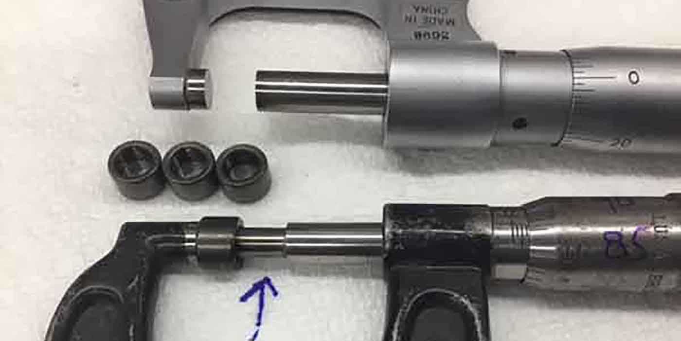
To measure the wall thickness of a main or rod bearing correctly the
location on the bearing that you measure and the tool you use will
determine the level of accuracy of the measurement. A micrometer with a
ball anvil must be used to fit the curvature of the bearing I.D., as
shown in Figure 1. Standard flat anvil micrometer, shown in Figure 2 will bridge across the curved I.D. and give false readings.

Micrometers with pointed or blade anvils and dial calipers should not
be used as they can give false readings and damage the bearing surface.
Obviously using an accurate, recently calibrated micrometer is a must
for reliable measurement.

Just as important as using the correct tool is the location on the
bearing that is measured. Crankshaft bearings should be measured 90° to
the parting line. By design most crankshaft bearings have an eccentric
design, which means the wall thickness at the parting line is not equal
to that at the 90° centerline.

The purpose of the eccentric design is
to compensate for casting distortion during operation, create a “wedge”
affect that promotes the formation of oil film, and for slight
tolerance differences of the jointing components. To determine the
amount of eccentricity, measure the bearing at the centerline and then
at approximately 3/8” above the parting line since some bearings may
also have an additional “relief” near the parting ends.

The amount of
eccentric dimension and the presence of a relief cut vary by engine
make and/or model. The centerline measurement determines the amount of
clearance between the bearing and crankshaft and is the common
dimension given when wall specifications are stated.

–Tech Tip courtesy of IPD (www.ipdparts.com)figure 1figure 2Figure 3

You May Also Like

Factors of Crankshaft Selection

From the high-performance powerplants propelling Top Fuel dragsters to the subdued engines found in family sedans and grocery getters, each crank must be tailored to, and appropriate for, its specific application.

We know a crankshaft plays a critical role in an engine’s performance, converting reciprocating motion into rotary motion while serving as the backbone of the entire system. It must be strong enough to withstand the continuous pounding of rods and pistons, yet possess enough elasticity to absorb vibrations and flex, albeit slightly, when needed.

Shop Solutions March 2024

I always keep a pair of needle nose pliers and a small, straight screwdriver in my blast cabinet to hold small parts when blasting.

Degreeing the Camshaft and Checking Valve-to-Piston Clearance

Jeff McCord of LinCo Diesel Performance walks you through degreeing a camshaft and checking valve-to-piston clearance.

Designing a Better LS Engine

After a customer wanted a Steve Morris Engines’ SMX in an LS version, Steve saw the upside and potential in the market, and a challenge to build a better LS.

Other Posts

The Importance of a Good Valve Job

The valve job ensures the mating surfaces of the valves and the seats properly control the air/fuel mixture.

Getting Better Cylinder Head Airflow

When it comes to improving horsepower and rpm, airflow has a lot to do with it, and it seems the job is one that’s never finished.

Horsepower and Head Gasket Technology

Head gaskets have one of the toughest job in an engine, and now we’re pushing them harder than ever, making it easier to expose the slightest weakness.

Inside the Development of Frankenstein’s F-Series LS Cylinder Heads

Right away, engine builders knew it was special.