The 2.4 L I4 PowerTech is a Neon engine variant based on the Chrysler engine that was designed originally for the Dodge and Plymouth Neon compact car. The naturally aspirated 2.4L 4-cylinder PowerTech engine provided 150 hp (110 kW) and 165 lb.-ft. (224 Nm).
In 2002, the Jeep Liberty was the first Jeep to use the two new Chrysler-developed Power-Tech engines — the 2.4L straight-4, (which was eliminated in 2006), and the 210 hp 3.7L V6.
The 2.4 L I4 PowerTech is a Neon engine variant based on the Chrysler engine that was designed originally for the Dodge and Plymouth Neon compact car. The naturally aspirated 2.4L 4-cylinder PowerTech engine provided 150 hp (110 kW) and 165 lb.-ft. (224 Nm).
In its short life, the engine was available in the 2002-’06 Jeep Liberty (first generation), as well as the 2004-’06 Jeep Wrangler, but was discontinued when Jeep introduced the Compass and Patriot small crossovers.
While those two crossovers also received a 2.4L I4 as a base engine, these were of the Global Engine Manufacturing Alliance (GEMA) joint-venture engine architecture and should not be confused with the Neon/ PowerTech engine of the same displacement.
Although the 2.4L PowerTech engine was only available for a relatively short time, the engine is
considered very reliable with no major problems associated with it.
2.4L PowerTech I4 Specs
The 2.4L PowerTech is a double overhead camshaft with hydraulic lifters and four valves per cylinder design. The engine is free-wheeling, meaning it has provisions for piston-to-valve clearance. However, valve-to-valve interference can occur if the camshafts are rotated independently.
Displacement: 144.0 CID (2,360 cc)
Stroke: 3.82” (97 mm)
Bore: 3.46” (88 mm)
Power: 150 hp (110 kW)
Timing Maintenance
Recommended timing belt replacement for the PowerTech 2.4L engine used in the Jeep Liberty/Wrangler is 120,000 miles.The following steps provide information on removal and replacement of the 2.4L I4 timing belt.
[inpost_gallery post_id=4944 group=”1″]
Timing Belt Replacement
1. Remove the air cleaner upper cover, housing and clean air tube.
2. Raise the vehicle on a hoist.
3. Remove the accessory drive belts.
4. Remove the crankshaft vibration dampener.
5. Remove the air conditioner/generator belt tensioner and pulley assembly.
6. Remove the timing belt lower front cover bolts and the cover.
7. Lower the vehicle.
8. Remove the bolts attaching the timing belt upper front cover and remove that cover.
Note: For more on removing components mentioned in steps 4-8, refer to the 2003Chrysler Service Guide.
Caution: When aligning crankshaft and camshaft timing marks, always rotate the engine from the crankshaft. The camshaft should not be rotated after the timing belt is removed because damage to the valve components could occur. And, always align the timing marks before removing the timing belt.
9. Before removal of the timing belt, rotate the crankshaft until the TDC mark on the oil pump housing aligns with the TDC mark on the crankshaft sprocket (trailing edge of sprocket tooth.) See Figure 1.
Note: The crankshaft sprocket TDC mark is located on the trailing edge of the sprocket tooth. Failure to align the trailing edge of the sprocket tooth to the TDC mark on the oil pump housing will cause the camshaft timing marks to be misaligned.
10. Install a 6 mm Allen wrench into the belt tensioner. Before rotating the tensioner, insert the long end of a 1/8” or 3 mm Allen wrench into the pinhole on the front of the tensioner. See Figure 2.
While rotating the tensioner clockwise, push in lightly on the tool until it slides into the locking hole.
11. Remove the timing belt.
Timing Belt Installation
1. Set the crankshaft sprocket to TDC by aligning the sprocket with the arrow on the oil pump housing.
2. Set the crankshaft timing marks so that the exhaust camshaft sprocket is half of a notch below the intake camshaft sprocket.
3. Install the timing belt. Starting at the crankshaft, go around the water pump sprocket, idler pulley and camshaft sprockets and then around the tensioner.
4. Move the exhaust camshaft sprocket counterclockwise to align the marks and to take up belt slack.
5. Insert a 6 mm Allen wrench into the hexagon opening located on the top plate of the belt tensioner pulley. Rotate the top plate counterclockwise. The tensioner pulley will move against the belt and the tensioner setting notch will eventually start to move clockwise. Watching the movement of the setting notch, continue rotating the top plate counterclockwise until the setting notch is aligned with the spring tang. Using the Allen wrench to prevent the top plate from moving, torque the tensioner lock nut to 22 ft.-lbs. (30 Nm). The setting notch and spring tang should remain aligned after the lock nut is torqued.
6. Remove the Allen wrench and torque wrench.
Note: Repositioning the crankshaft to the TDC position must be done only during the clockwise rotation movement. If TDC is missed, rotate a further two revolutions until TDC is achieved. Do not rotate crankshaft counterclockwise as this will make verification of proper tensioner setting impossible.
7. Once the timing belt has been installed and the tensioner adjusted, rotate the crankshaft clockwise two complete revolutions manually for seating the belt, until the crankshaft is repositioned at the TDC position. Verify that the crankshaft and the crankshaft timing marks are in proper position.
8. Check to see if the spring tang is within the tolerance window. If so, the installation process is complete and nothing further is required. If the spring tang is not within the tolerance window, repeat steps 5 through 7.
9. Install the timing belt front covers and bolts.
10. Install the air conditioning/generator belt tensioner and pulley.
11. Install the crankshaft vibration dampener.
12. Install the accessory drive belts.
13. Install the drive belt splash shield.
14. Install the air cleaner housing, upper cover and clean air tube.
Other Liberty Issues
In 2008, Chrysler revised its 2.4L cylinder head bolt re-torque procedure. The information supersedes the previous technical bulletin, dated March 25, 2005. The previous bulletin should be removed from your files.
The latest bulletin applies to vehicles equipped with a 2.4L engine built between Feb. 1, 2004 and April 5, 2005.
Whenever re-torqueing the cylinder head bolt(s), be sure to follow the torque sequence as outlined below. If there are no external signs of damage to any parts, attempt the procedure below before replacing a cylinder head, cylinder head bolts or cylinder head gasket.
1. Using a 6” wobble plus extension friction ball and shallow socket and following the torque sequence loosen one bolt at a time to 0 torque and then torque that same head bolt to 60 ft.-lbs. See Figure 3.
2. Repeat step 4 for every head bolt, one bolt at a time in sequence.
3. Verify that each head bolt is at 60 ft.-lbs. before performing the next steps.
4. After all the head bolts have been verified to be torqued to 60 ft.-lbs., follow the torque sequence and turn the head bolts an additional 90° (1/4 turn).
5. Following the appropriate procedures to install the cylinder head cover.
Some or all of the technical information was provided by the Automotive Parts Remanufacturers Association (APRA). More information and technical bulletins on vehicles equipped with a 150-hp 4-cylinder engine are available through APRA; call 703-968-2772![]() or visit www.AutoBulletins.com.
or visit www.AutoBulletins.com.
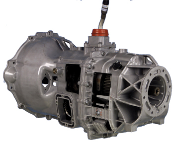
Transmission Upgrade
In 2005, the Jeep Liberty and Jeep Wrangler were upgraded with a NSG 370 six-speed manual transmission, replacing two five-speed manual transmissions previously used in these applications — the NV1500 and the NV3550 — in an effort to reduce cost and complexity.
The new transmission is a member of the six-speed NSG 370 family, similar to the one used in the Chrysler Crossfire — the first six-speed for the Chrysler brand. The NSG six-speed manual transmission provides a 4.46:1 first-gear ratio, versus the 3.85:1 and 4.04:1 ratios of the five-speed transmissions it replaces, for improved launch and traction.
Jeep said that the NSG 370 six-speed manual transmission provides optimal shift quality, improved quietness and high quality. A new dual-ratio transmission shift-tower system allows packaging of the six-speed shift pattern within the existing Jeep vehicles, and it is tuned for optimized shift quality. For smooth operation, the first and second gears have triple-cone synchronization, the third and fourth gears feature double-cone, and the fifth and sixth gears single-cone synchronization.
Chrysler engineers also said the hard-finished gears allow for quiet operation, and the two-piece aluminum case with integrated clutch housing assures powertrain stiffness and light weight. The new first-gear ratio, combined with six-speed step spread, allows optimization of axle ratios for fuel economy and performance.
Source: Chrysler Group LLC.


