Variable Valve Timing (VVT) has been incorporated into many late model import and domestic engines, including single overhead cam (SOHC), dual overhead cam (DOHC) and even pushrod V8s such as GM’s GEN IV 5.3L and 6.0L engines. It is a technology that offers performance, emissions and fuel economy advantages for everyday driving, but it also creates some challenges for engine builders. The technology allows camshaft and valve timing to change with engine speed and load so the engine can develop more high speed power while also getting better fuel economy under light load conditions. Retarding exhaust valve timing can produce an exhaust gas recirculation effect, which eliminates the need for a troublesome EGR valve on many engines.
On DOHC engines, the powertrain control module can advance or retard the intake and exhaust cams separately. This changes the centerline between the cams and the lobe separation angle, which in turn changes valve overlap. On SOHC and pushrod engines, the same cam operates both the intake and exhaust valves so advancing or retarding the cam changes both the intake and exhaust timing simultaneously.
There are a few VVT applications that use an electric actuator to advance or retard cam timing (Lexus, for example), and some others that raise rocker arms to change both valve timing and lift (Honda VTEC, for example). Another variant is the VVT system in the Dodge Viper V10 that uses a camshaft within a camshaft to vary valve timing and lift. But most of the VVT systems that Engine Builder readers are most likely to encounter have hydraulically-actuated cam phasers.
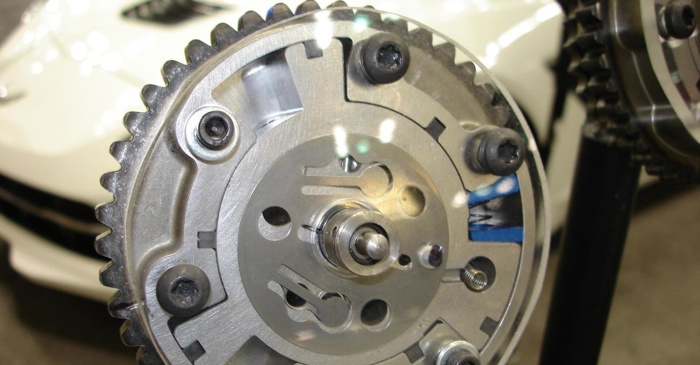
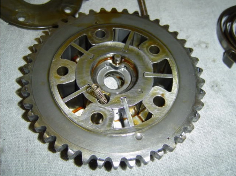
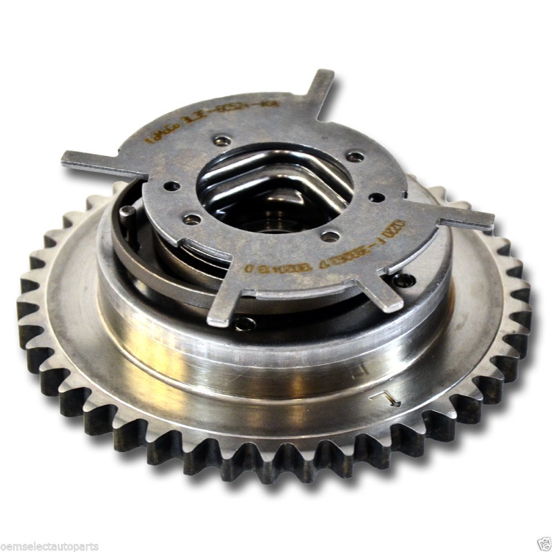
A cam phaser changes camshaft and valve timing by rotating the relative position of the camshaft slightly fore or aft compared to its normal base timing setting. The phaser is part of the cam drive system and is mounted on the cam drive gear or sprocket. There are several basic designs:
Helical gear phasers. These are used on many of the older applications and are essentially “on” or “off” actuators. When oil pressure is applied to the gear mechanism inside the phaser, it forces the helical gear to move. This typically retards cam timing 20 to 30 degrees. A spring then returns the cam back to its normal position when oil pressure is relieved.
Lobed rotor phasers. With this design, the phaser housing usually has four chambers with a movable four lobed rotor inside. When oil pressure is routed into the chambers, it pushes the lobed rotor one way or the other to advance or retard cam timing. Many of these units provide incremental timing changes that can vary from zero degrees of advance or retard up to full advance or retard. Timing changes can range from 20 degrees to as much as 60 degrees on some applications.
Vane rotor phasers These function pretty much the same as a lobed rotor phaser by offering incremental timing advance or retard as oil pressure is applied to the chambers on either side of the vanes. The phaser usually has five vanes that protrude outward from the rotor, with each vane being located within its own oil cavity.
With lobed and vane style phasers, there is an internal dowel pin that holds the rotor in the base timing position when no oil pressure is applied. This prevents rotor movement and noise when the engine is started and when it is idling. When oil pressure is applied to the phaser, it pushes the dowel pin out of its locating hole and allows the rotor to move.
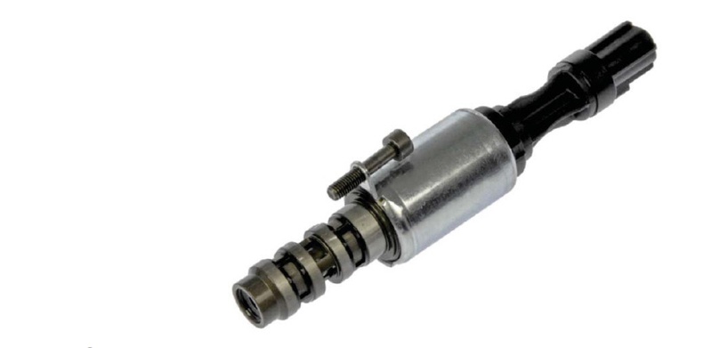
Most VVT systems are not engaged when the engine is idling and remain in the locked or base timing setting. Also with hydraulically-actuated cam phasers, the VVT system is usually not active until the engine reaches normal operating temperature. As engine speed and/or load change, the PCM looks at its various sensor inputs and commands the oil flow control valve solenoids to open. The oil flow control valve solenoids are located near the phasers on the timing cover or valve covers. When the solenoid valve opens, oil pressure is routed to the phaser and cam timing is advanced or retarded depending on the design of the phaser and oil control valve, and how oil pressure is routed in the chambers inside the phaser. On applications that offer incremental changes in cam timing, the oil flow control valve is pulse width modulated. Changing the duty cycle of the solenoid controls oil flow through the phaser and how much cam timing is advanced or retarded.
As simple as it all sounds, any number of things can cause VVT problems:
Electrical problems with the supply voltage, ground connection or wiring to the oil flow control solenoid can prevent the cam phaser from doing its thing.
Low oil pressure due to a worn oil pump or worn cam bearings may prevent the cam phaser from developing sufficient internal pressure to rotate the cam.
Debris, sludge or varnish that restricts or blocks the oil flow control valve or inlet screens can also interfere with oil flow to the phaser, preventing it from working properly. The same thing can happen if the phaser itself is clogged with sludge, debris or oil varnish deposits.
Using the wrong oil viscosity in the engine may also make the phaser slow to respond, causing various fault codes to set.
Physical wear or damage inside the cam phaser housing may prevent it from rotating, cause it to stick, or make the unit noisy. A broken return spring may prevent it from returning to base timing.
Think of a lobed or vane style cam phaser as a backwards operating gerotor style oil pump. A gerotor oil pump produces oil pressure as the pump rotates. By comparison, a cam phaser rotates when oil pressure is applied to the rotor. Because of this, the clearances between the housing and rotor have to be fairly tight otherwise you end up with internal pressure losses that affect the operation of the unit.
With lobed rotor and vane style cam phasers, wear in the phaser housing, vanes or lobes reduce the unit’s ability to hold pressure and function normally. The dowel pin that holds the rotor in its neutral position may also become worn or shear off, or the hole that the pin fits into may become elongated or worn preventing it from holding base timing. This can make the phaser noisy at idle as well as cause erratic valve timing.
Some late model Ford 4.6L, 5.4L and 6.8L engines have a serious noise problem at idle due to wear inside the VVT cam phasers. The engine often clatters like an old diesel at idle because of the cam phasers. Often, the right phaser is noisier than the left.
Ford TSB 06-19-8 covers this cam phaser knock problem, and recommends replacing the phasers to eliminate the idle noise. But on many high mileage engines, the cam phasers may not be functioning properly because of worn cam bearing bores in the cylinder heads. There are no replaceable cam bearings on these engines, so if the bores are worn the heads have to be machined to accept bearings, or the bores need to be welded and re-machined back to the original dimensions to restore normal oil pressure to the cam journals and cam phasers. Replacing the original equipment oil pump with a higher volume pump can also help remedy this situation.
Replacing Cam Phasers
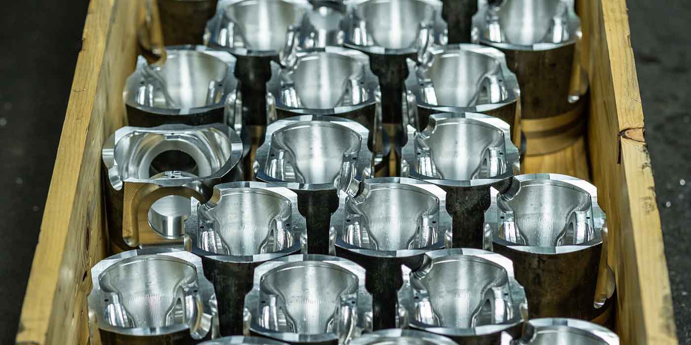
Cam phasers are expensive units to replace, costing anywhere from $100 to nearly $300 each depending on the application. Several aftermarket suppliers have replacement cam phasers in their product lines, but most of the phasers that are currently available are for domestic engines (Ford, GM and Chrysler). If you’re rebuilding an import engine and need to replace the phasers, they may be harder and more expensive to source.
Like any other component on an engine, the cam phasers need to be disassembled, cleaned, inspected and tested before they are reused on an engine. Reusing a bad cam phaser is no different than reusing a worn oil pump. It will cause problems and end up costing you money and possibly a customer.
One major engine rebuilder we contacted for this article said they rebuild or replace every cam phaser on every engine they remanufacture. They never take a chance on reusing a cam phaser until it has passed their internal inspection and test procedures. They have had to develop their own cam phaser reman procedures as well as sources for their own custom-made component parts (which they would not divulge). The engineer I spoke to said they have invested hundreds of hours researching and studying cam phasers to develop their own test and repair procedures. Even then, it’s often more economical to replace a badly worn or damaged phaser than to attempt to repair it.
Rebuilding a cam phaser can be much less costly than buying a new phaser, but for now most engine builders can’t source internal repair parts for phasers. Phaser repair parts are not available from either the aftermarket or OE suppliers. Although some intrepid supplier might jump on this as a new market opportunity, rebuilding a worn or damaged cam phaser is not as easy as it sounds.
currently the only repair
option available to most engine builders who need to replace a worn or defective phaser.
Why not? For one thing, there are no repair specifications from the automakers or OEM suppliers regarding internal tolerances for cam phasers. Phasers are treated as sealed units that are supposed to be replaced if they are worn or defective. Consequently, if you want to rebuild cam phasers, you first have to figure out what the acceptable tolerances are supposed to be by taking apart and measuring new phasers.
The next challenge is finding a source for any internal components that may need to be replaced such as dowel pins, helical gears, return springs, rotors or individual vanes that may be worn or damaged. The cost to manufacture these parts will partially determine the economics of rebuilding the phaser. If it costs too much to source custom parts from an outside supplier, or to make the parts yourself using CNC equipment or other shop equipment, it may not make economic sense to rebuild phasers in-house.
You also have to develop your own repair procedures for re-machining the phaser housing or rotor to restore normal tolerances, all of which adds labor cost to the process.
Finally, you have to develop a reliable method for testing a rebuilt phaser BEFORE it goes back on an engine. Skip this vital step and you could end up regretting all the time and effort you’ve put into trying to save money rebuilding your own phasers. So for now, most engine builders have no other option but to buy a new replacement phaser if a phaser on an engine they are rebuilding is worn or damaged.
Performance engine builders face a different challenge with variable valve timing and cam phasers. On a stock engine that is used for everyday driving, VVT can advance and retard cam timing on the go, typically 20 to 30 degrees and as much as 60 degrees on some applications as we mentioned earlier. With this much cam movement, valve-to-piston clearances can be limited. It may not be possible to install a camshaft with increased lift and/or duration in certain VVT applications with a major risk of a valve kissing a piston.
Machining deeper valve relief pockets into the tops of the pistons may be a work around in some applications, but for significant increases in valve lift and duration, you have to limit the amount of cam rotation to prevent the valves from hitting the pistons.
Several aftermarket suppliers now offer various types of cam phaser limiter kits to overcome this problem. Some of these kits reduce the amount of timing change to 20 degrees or less. This allows the engine to retain some of the advantages of variable valve timing such as retarding cam timing at higher RPMs for more power and a broader torque curve. Other kits essentially lock the cam phasers so they function like a solid gear. The locker kits include a lockout plug that fits between one or more of the lobes or valves on the rotor to prevent the rotor from moving, or a steel lockout plate with prongs that engage the phaser rotor to prevent it from moving.
Cam phaser limiter and lockout kits are currently available for 2005 and up Ford 4.6L and 5.4L modular V8s, 2011 and newer Ford 5.0L Coyote engines, 2007 and up General Motors Gen IV engines with VVT, and late model Chrysler 5.7L, 6.1L and 6.4L HEMI engines. More applications will likely be added in the future.
On late model Ford 4.6L modular 3-valve V8s, for example, the cam phasers can alter cam timing while the engine is running to optimize fuel economy, performance and emissions. During part throttle operation, the cams can be rotated 20 to 40 degrees to reduce pumping losses for better fuel economy. When the engine is lugging hard, it may retard timing even more (up to 60 degrees) to reduce oxides of nitrogen (NOx) emissions. At wide-open throttle, timing retard is typically around 9 degrees on these engines. That’s fine for everyday driving, but not the sort of thing you want in a high-revving performance engine. And as we said earlier, there’s not a lot of valve-to-piston clearance in these engines so it restricts the amount of valve lift, duration and overlap you can use before things start to clash.
Disassembling the cam phasers and installing a locking plate or lockout plugs essentially defeats the VVT system and converts the phaser to a solid gear. You lose some of the benefits of variable valve timing and you have to reprogram the stock computer so it won’t attempt to change cam timing or set VVT-related fault codes. However, you gain the ability to build and tune the engine like an engine without variable valve timing for a specific power and torque curve. You can install a much hotter camshaft with increased lift and overlap without worrying the engine might eat a valve or destroy a piston because VVT shifted the timing too far.
Another advantage of using a cam phaser limiter or lockout kit is that the kit can always be removed at some future date if the vehicle owner wants to go back to a stock VVT setup. A cam swap might also be necessary depending on the cam specs, lift and duration.
As time goes on, VVT will likely become standard on almost all engines. Also, we’ll probably see fewer hydraulic cam phasers and more electronic cam phasers because they are faster and more responsive. General Motors has indicated it will be using more electronic cam phasers on its VVT systems starting in 2016 and later model year vehicles. VVT is also being integrated into engines that have variable displacement or displacement on demand, some of which use variable valve lifters to change valve lift and duration.
As the technology continues to become more common on the street, it’s likely repair methods will keep pace in the machine shop.
For an enhanced version of this article, with additional information, see our digital version online at www.EngineBuilderMag.com