injection pump to deliver fuel to each piezo electric fuel
injector via a high pressure common fuel rail, one rail per bank.
In 2003, increased emission standards forced Ford to stop offering the 7.3L Powerstroke in MY Ford trucks. Instead, the company turned to the up and coming 6.0L Power Stroke. Little was known just how big of a disaster this would be for Ford’s reputation.
While the 6.0L was only offered for a period of four years in the Super Duty truck, many problems arose from the new Hydraulically acutated, Electrically controlled Unit Injector (HEUI) engine design that would cripple the dependability of the Ford diesel pickup. Even though the 6.0L was cutting edge technology producing more power in a smaller package, the engine was plagued with various hiccups that destroyed its reputation and still carries this reputation with it today. For the 2008 MY Ford Super Duty pickup, a new engine, the 6.4L Powerstroke would emerge. But, how much is really known about the engine? The 6.4L engine was very short lived and only offered until 2010.
Before going any further, there is something that you have to realize. Manufacturers of on-road diesel engines were grasping for straws. Clean air standards for diesel engines have become tougher to meet. The biggest factor for Clean Air of a diesel engine is to lower NOx gas and particulate matter from the exhaust system. The 6.0L was designed to lower NOx emissions by incorporating an EGR (Exhaust Gas Recirculation) system. The engine was smaller in
displacement, with four valves per cylinder, direct injection and variable geometric turbocharger. NOx gas emissions could be drastically reduced by reintroducing exhaust gas back into the engine to be re-burned. The only problem is that exhaust gas displaces the oxygen causing a cooler burn, which may lower NOx but in turn cause soot. So, the 6.0L engine became a problem because it would not meet particulate matter standards that would go into effect for 2008. The 6.4L would take its place with a little more displacement, four valves per cylinder, sequential turbo system, high-pressure common rail fuel injection, EGR and DPF.
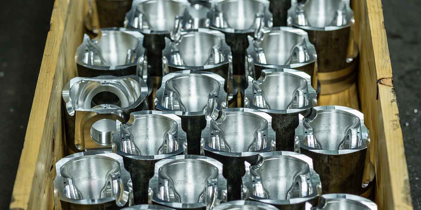
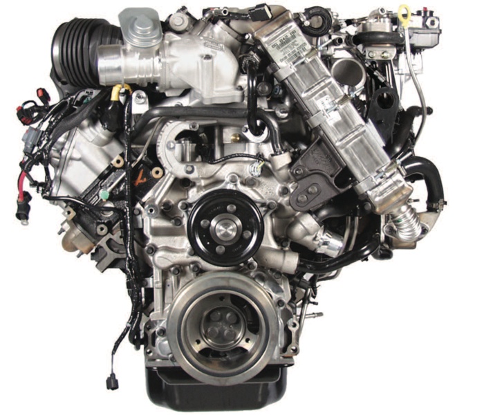
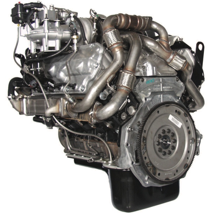
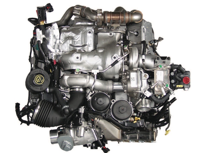
When you open the hood of a 2008 Ford truck, you realize that the 6.4L was a big change. You may not even recognize any parts of the engine that you are commonly familiar with other than maybe the turbo or the air filter. The 6.4L was definitely unique, but just how different was it from the 6.0L? The short block of the 6.4L engine is basically the same as the 6.0L. The bore was increased from 3.74” to 3.87” with the stroke remaining the same at 4.134” The piston design was very similar, but compression ratio was lowered to 17.5:1 instead of 18.0:1. Firing order remained the same being 1,2,7,3,4,5,6,8. The 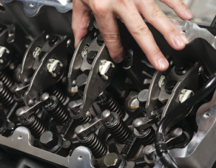 passenger side is the odd numbered cylinders 1,3,5,7 and the driver’s side cylinders are even numbered 2,4,6,8.
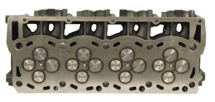
The other components of the engine are where the major changes take place. The cylinder heads are still designed with four valves per cylinder, but the 6.4L is not a HEUI design, it is a high-pressure Common-Rail.
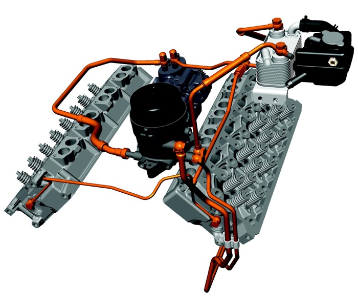
High-Pressure Common-Rail consists of a network of precision components that enable fuel to be injected under extreme pressure, which ranges from 5,000 psi to 30,000 psi. The high-pressure fuel pump is driven by the rear gear train and mounted in the same place as the HPOP in the 6.0L. The high-pressure fuel pump consists of a VCV (Volume Control Valve), which controls the volume of fuel entering the pump and a PCV (Pressure Control Valve), which controls pressure the pump produces. As fuel enters the pump, it is then
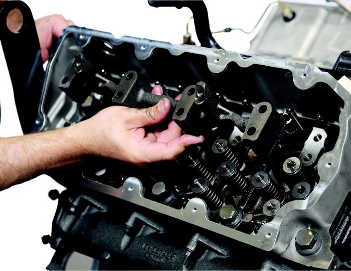
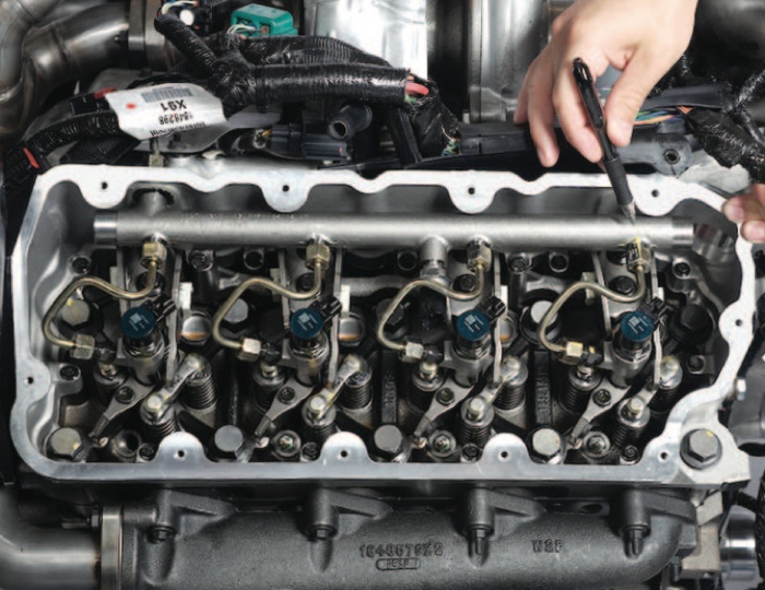
pressurized and sent to the fuel rails attached to the cylinder heads located underneath the valve covers. The 6.4L has a Piezo Electric injector mounted in the center of the valves directed in the middle of the combustion chamber just like the 6.0L. A high-pressure line connects the high-pressure fuel rail to the injector. The injector is held in place with a hold down clamp and is sealed with an O-ring. The piezo electric injectors are extremely precise with the ability to actuate five times per combustion event.
The path of fuel flow is also unique compared to the 6.0L. The fuel pump on the driver’s side frame rail takes fuel out of the tank and pressurizes it to the secondary filter housing located on top of the engine much like the 6.0L. From the secondary filter housing, fuel is then sent to the high-pressure fuel pump. Returning fuel from the high-pressure pump joins fuel returning from the injectors from lines in the front of the cylinder heads. The returning fuel goes through a secondary cooling system, which is located on top of the turbo at the firewall of the driver’s side. This is done because high fuel pressures increase the temperature of diesel fuel.
Hot fuel will lose its lubricity and lock up the high-pressure pump. The secondary cooling system consists a fuel cooler that is circulated with engine coolant, a coolant bottle and a circulation pump, which is mounted behind the fuel radiator, which is mounted on the driver’s side of the charge air cooler. When fuel temperature reaches 77 degrees F, the coolant pump turns on. When fuel temperature reaches 68 degrees F, the pump turns off. If fuel temperature reaches 151 degrees F, the engine fan comes on, and if the fuel temperature reaches 194 degrees F, the engine loses power and the check engine light
comes on and doesn’t go off.
Fuel also has to be super clean for the common-rail system. The primary fuel filter is rated at 10 micron and the secondary fuel filter is rated at 4 micron. Any contaminants larger than 4 micron can score the components in the fuel system.
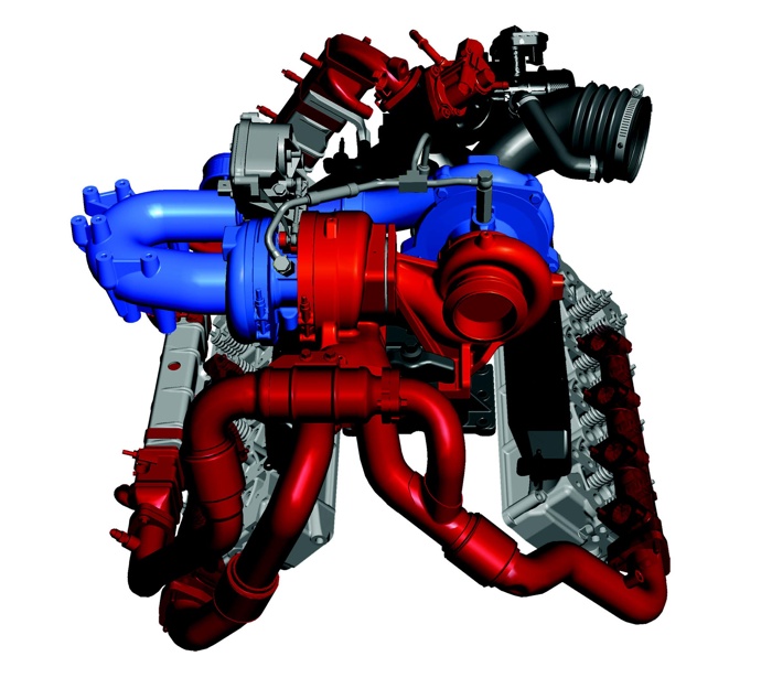
Another interesting change was the function of the turbocharger. The 6.4L was often referred to as twin turbo, but the proper name would be a sequential turbo system. The object of the sequential turbo system is to take a small turbo and feed a larger turbo. Some may refer to this system as “compounding.” When you feed a larger turbo with a smaller one, you are trying to produce optimum boost with little or no turbo lag. The smaller turbo is considered low pressure and the bigger turbo high pressure. The high-pressure turbo 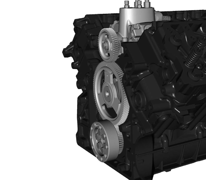 contains vanes much like the turbo from the 6.0L. As the vanes open and close, they control the effective size of the housing. The vanes are controlled by an actuator linked to a pivot arm, which is connected to an unison ring that moves the vanes. The actuator is controlled by the PCM, which is cooled by the coolant system to protect the electronics.
Here is a brief summary of how the turbocharging system works:
• Air enters the low-pressure turbo from the air filter
• The low-pressure turbo compresses the air and sends it through an extension tube where it enters the high-pressure turbo
• The high-pressure turbo further compresses the air and sends it to the CAC (Charge Air Cooler) before
entering the intake manifold
During operation at low engine speed, there is little energy available from the exhaust to generate boost. In order to utilize the small amount of exhaust energy, the turbo actuator will be commanded to close the vanes of the high-pressure turbo. This causes a pressure increase in the exhaust housing of the turbo which will increase the turbine wheel speed causing the high pressure turbo to act like a small one and provide boost. At medium engine speed, the actuator will be commanded to partially open the vanes. This will provide the correct amount of boost for proper engine operation and EGR function. During high engine speed, the actuator will be commanded to open the vanes completely and the turbo will act as a big turbo with minimum restriction while providing maximum boost.
The exhaust system routing also influences turbo operation and proper emission function. As exhaust exits the cylinders, it travels into the exhaust manifolds and then into the exhaust “up” pipes. The “up” pipes feed exhaust into the high-pressure turbine housing and then into the low-pressure turbine housing where it exits into the “downpipe,” which carries the exhaust to the exhaust system.
On the passenger side “up” pipe, there is a branch that carries exhaust through an EDOC (EGR Diesel Oxidation Catalyst) and then to the horizontal EGR cooler. The purpose of the EDOC is to crack hydrocarbons of the exhaust gas before entering the EGR coolers. Exhaust gas then flows out of the horizontal cooler and enters the EGR vertical cooler.
 As exhaust gas exits the vertical cooler, it is stopped by the EGR valve where it will enter the engine when the PCM commands the EGR valve to open. The purpose of the EGR function is to lower NOx emissions of the exhaust gas by letting the engine re-burn the exhaust gas. The purpose of the two EGR coolers is to lower temperature of the exhaust gas before it enters the intake manifold. Both of the coolers along with the EGR valve is cooled by coolant from the cooling system. Under load, exhaust gas temperatures can be extremely hot and the coolers can remove up to 850 degrees F of temperature before reaching the intake.
When the exhaust gas exits the low-pressure turbo into the downpipe, it passes into the DOC (Diesel Oxidation Catalyst). The purpose of the DOC is to remove hydrocarbons but also ramp up temperature to burn off soot in the DPR (Diesel Particulate Filter). The DPF filters particulates from the exhaust gas known as soot. Soot builds up over time and must be burned and turned into gas. This process is known as regeneration.
There are two types of regeneration: passive and active. Passive regeneration happens at normal driving when the exhaust temperature is hot enough for the DOC to burn off the soot build up in the DPF. Active regeneration
occurs when the DPF becomes restricted and the exhaust temperature is not hot enough such as short distance trips or long idle time. During active regeneration, a change is heard in the exhaust system and the engine idle ramps up. The injectors are commanded to inject fuel into the engine on the exhaust stroke, which will put raw fuel into the DOC. This causes the DOC temperature to increase, which will burn off soot trapped in the DPF.
One thing to note here is that the exhaust tips at the passenger side rear wheel have windows notched in them. These windows are known as “tip diffusers,” which are used to draw in cool air to help cool the exhaust gas exiting the tips. Temperatures at the tip can become very high, so this helps cool the exiting gas. It is not recommended to change or modify these tips and keep them clear of debris.
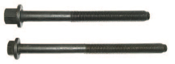
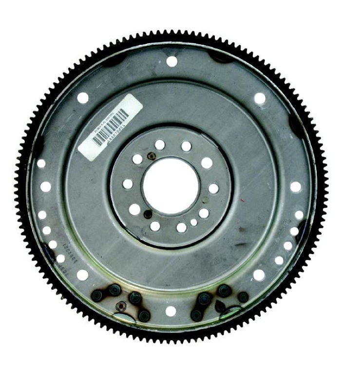
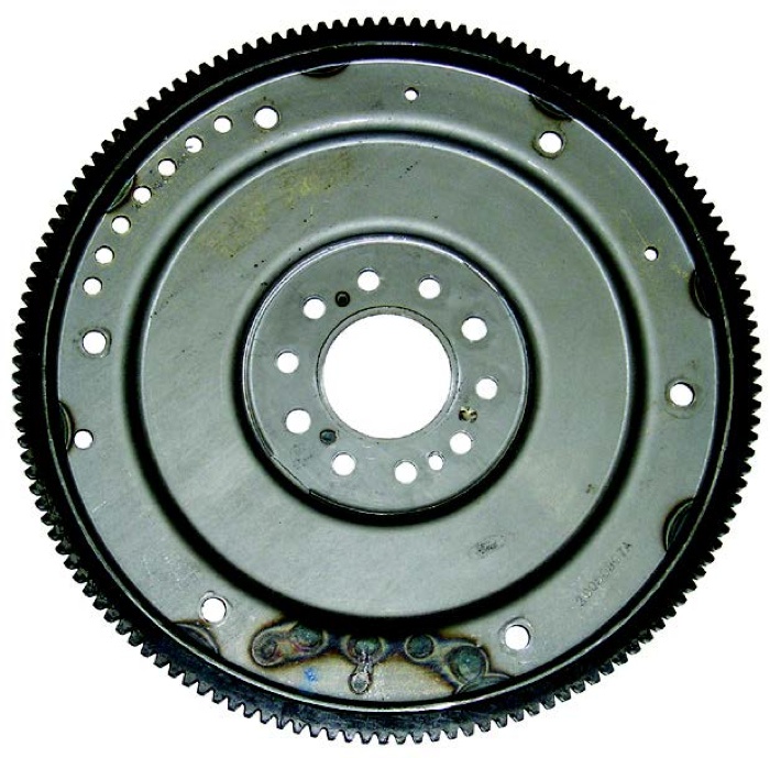
The 6.4L was a juiced up 6.0L and Ford had tried to address a lot of the failures of the 6.0 liter in this engine. The 6.4 had a totally reconstructed EGR cooler system, bigger head bolts, different turbo configuration, different fuel system, bigger flexplate, and cooling system. These were all in response to the fact that the 6.0L had too small of head bolts, a turbo that would stick and had to be removed and cleaned, an EGR cooler that would failand injectors that would stick due to the HEUI design.
When it really comes down to it, the only thing the 6.4L has in common with the 6.0L are a few components
The 6.4L Power Stroke diesel uses two fuel filters and a standalone fuel cooler system.
Fuel Supply System Includes:
• Horizontal Fuel Conditioning Module (HFMC)
• Chassis-mounted 10 micron fuel filter
• Engine-mounted 4 micron fuel filter
• Water separator
• Fuel cooler
of the short block. It was best described as a 6.0L on steroids.
Very special thanks to Brent Burich and all the technical experts at Blue Diamond for invaluable assistance with this project.
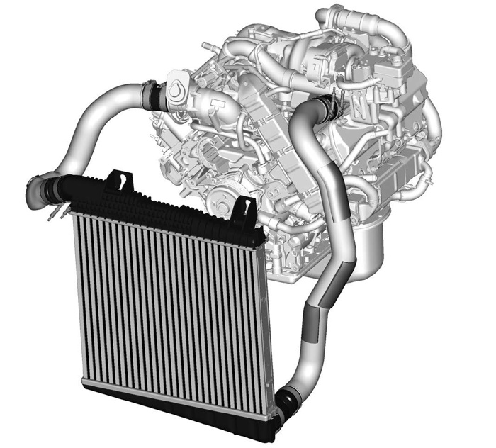
The series sequential turbocharger is a low pressure/high pressure design working with a turbocharger actuator on the high pressure turbine controlling the boost pressures.
The charge air cooler is utilized to reduce the temperature of the pressurized air therefore inducing a cooler/denser air charge into the intake manifold for maximum efficiency.
An air filter/filter minder combination is utilized to clean the incoming air and provide a means for monitoring the conditions of the air filter via the air filter minder.
The EGR system is designed to reduce exhaust emissions.
Key Air Management System Components:
• Series Sequential Turbocharger
• Charge Air Cooler
• Intake Manifold
• Air Filter/Filter Minder
• Exhaust Gas Recirculation (EGR) System
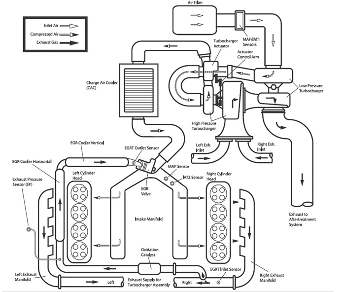
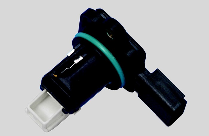
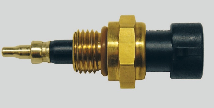
System Flow: Air enters the system through the air filter where particles are removed from the air. The air filter has a filter minder on it to warn the operator of a restricted air filter. After the air is filtered, the mass of the air and temperature are measured by the mass air flow sensor (MAF) and the intake air temperature sensor #1 (IAT1).
The filtered air is then directed past the crankcase ventilation system where the crankcase vapors and fresh air are mixed.
After mixing with crankcase vapors the fresh air mixture is drawn into the low pressure turbocharger compressor then the compressed air is sent to the high pressure turbocharger where it is further compressed before being sent to the charge air cooler (CAC). The CAC cools the compressed air via an air-to-air cooler, then the condensed air passes through the EGR throttle, mixes with cooled EGR gases, then enters the intake manifold. The intake manifold directs the cooled air to the intake ports of the cylinder heads. The burned air fuel mixture is pushed out of the cylinder into the exhaust manifold which collects the exhaust and routes it to the high pressure turbocharger’s turbine wheel. The exhaust up pipe, connected to the passenger side exhaust manifold, has a passage that directs exhaust to the exhaust gas recirculation (EGR) coolers and then to the EGR valve. The EGR valve controls the flow of exhaust in the intake system where the gases are mixed with intake air to reduce the NOx (Oxides of Nitrogen) emissions and noise. The hot and expanding exhaust gases that are routed to the series of sequential turbocharger turbines spin the turbine wheels then spin the compressor wheels via common shafts.
The series sequential turbocharger for the 6.4L Power Stroke diesel is designed to provide boost control at low and high speeds for improved throttle response. The turbocharger actuator is used to control the position of the variable vanes inside the high pressure turbocharger’s turbine housing.
When the vanes of the turbocharger are closed, the engine will have a higher exhaust back pressure and create more heat, which will in turn warm the engine fast in the cold ambient conditions. NOTE: The oxidation catalyst in the exhaust pipe for the EGR system is utilized to crack hydrocarbons before they enter the EGR system.
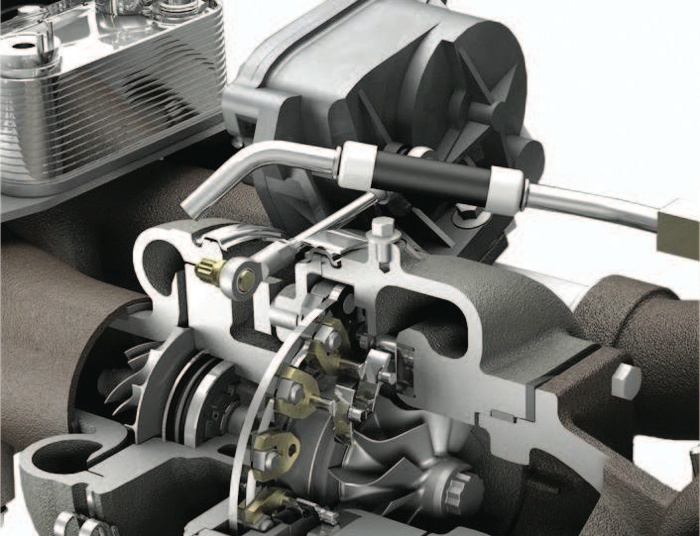
controlled by the turbocharger actuator. The high pressure turbocharger’s turbine housing contains vanes that control the effective size of the housing. These vanes are controlled by the turbocharger actuator by way of a control arm. The control arm connects the actuator to a pivot shaft, which connects to the unison ring that moves the vanes.
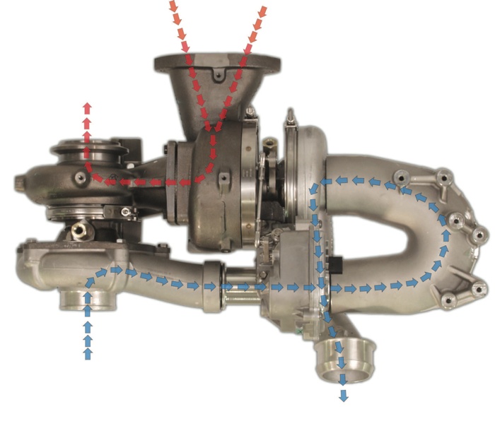
turbocharger from the air filter. The low pressure turbocharger compresses the air and sends the air through the extension tube and the crossover tube prior to entering the high pressure turbocharger. The high pressure turbocharger further compresses the air and sends the air to the charge air cooler (CAC) where the air is cooled by an air-to-air cooler prior to entering the intake manifold.
Exhaust Airflow (Red): Exhaust gas enter the high pressure
turbocharger turbine housing after being directed through the exhaust up-pipes at the rear of the engine. The high pressure turbocharger turbine contains the vanes which are controlled by the turbocharger actuator. These vanes continually change the velocity of the exhaust gas in the high pressure turbocharger turbine. After the gas has passed through the high pressure turbocharger turbine it immediately enters the low pressure turbocharger turbine. Once the exhaust gas has powered the low pressure turbocharger turbine the exhaust exits through the housing toward the rear of the engine where it is directed to the exhaust aftertreatment system.
designed to lower the temperature of the air coming out of the turbocharger outlet before entering the intake manifold.
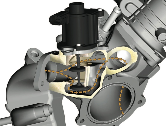
• The EGR valve has two valves connected by a common shaft.
• Cooled exhaust gas enters the lower opening of the EGR valve after leaving the vertical EGR cooler.
• When the valve opens it allows the cooled exhaust gas to flow through two passages; one is through the upper opening of the EGR valve (upper vlave) and the other is through a passage below the EGR valve (lower valve)
• Both passages merge together prior to being mixed with the filtered incoming air before being sent to the intake manifold.
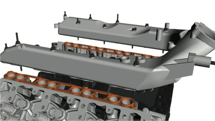
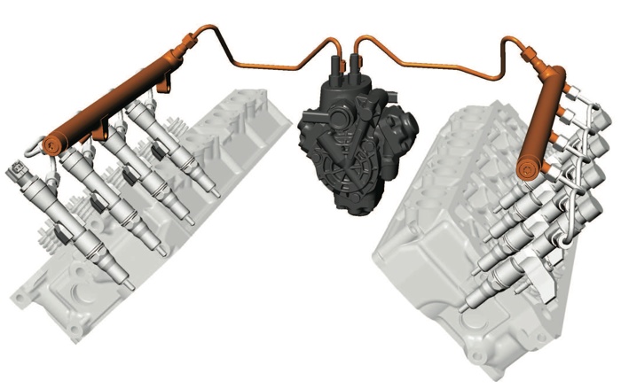
Once the high pressure fuel injection pump pressurizes the fuel it is routed to two (2) high pressure fuel rail
supply tubes, one for each bank. The high pressure fuel rail supply tubes rout the fuel to the high pressure fuel rail located under the valve cover. The high pressure fuel rail inlet protudes through the valve cover spacer at the back of the engine and oil is sealed by a rubber seal. The high pressure fuel rail routes fuel to each of the four fuel injectors through four separate fuel injector supply tubes all located under the valve cover.