Direct injection is becoming standard on more and more late-model vehicles in both gasoline and diesel versions. These systems can be a diagnostic challenge, but with the right foundation, problems can be solved profitably.
A better understanding of how they work can help you help your installer customers do a better job. And, as direct injection becomes more common in your shop, you may need to address how you rebuild these engines.
Gasoline direct injection in its current form has been around since 1997. During the next 10 years, Volkswagen, BMW, Mercedes Benz and many others introduced engines with direct injection. Today, almost all new engines have direct injection.
When the early direct-injection engines hit the three-year or 30,000-mile mark, some developed drivability problems due to carbon build-up on the necks of the intake valves. Typical symptoms were misfire codes, stumbling and suspicious fuel trim numbers.
Carbon deposits cause the air to tumble into the combustion chamber, and this turbulence causes the fuel and air mixture to be unevenly distributed. When ignited, the flame front can be erratic, leave unburned fuel and create hot spots in the combustion chamber.
What Causes Carbon?
In the late ’90s and early 2000s, TSBs related to carbon deposits on the valves were few and far between. There are three reasons why direct injection engines are more prone to carbon deposits. One reason is unique to direct injection, and the remaining two are problems for port fuel injection engines too, but are made worse by direct injection.
The main reason is that fuel and added detergents are not hitting the back of the intake valves. By injecting the fuel directly into the cylinder instead of at the back of the valve, the gasoline and detergents can’t clean the valve and port.
Second, leaner mixtures and higher combustion pressures can make the problem worse over time. A direct fuel injection motor produces more energy from a given amount of fuel and air than a port fuel injection engine. Today’s engines operate on a ragged edge between optimal efficiency and a misfire. There is not much room for error like hot spots in the combustion chamber or a worn spark plug.
When a hot spot or sub-optimal flame front is created due to turbulent air, the amount of unburned fuel in the combustion chamber increases. When the valve opens during the intake stroke, it might come in contact with these byproducts, and unlike the exhaust valve, the gases passing by are not hot enough to burn it off.
Third, the intake valve goes into the combustion chamber, regardless if it is port fuel injected or direct injected. When ia does, for that small period of time, it is exposed to combustion byproducts that can stick to the neck of the valve. If the last combustion cycle was less than optimal, the intake valve is exposed.
Some direct injection vehicles with variable valve timing can expose the valve to combustion byproducts as the valves adjust, which creates a scavenging effect to either pull or leave behind a small amount of exhaust gases in the chamber to control NOx emissions. Also, some turbocharged direct injection engines will leave the intake and exhaust valves open at the same time in order to keep the turbo spinning to reduce lag.
Direct Deposit Problems
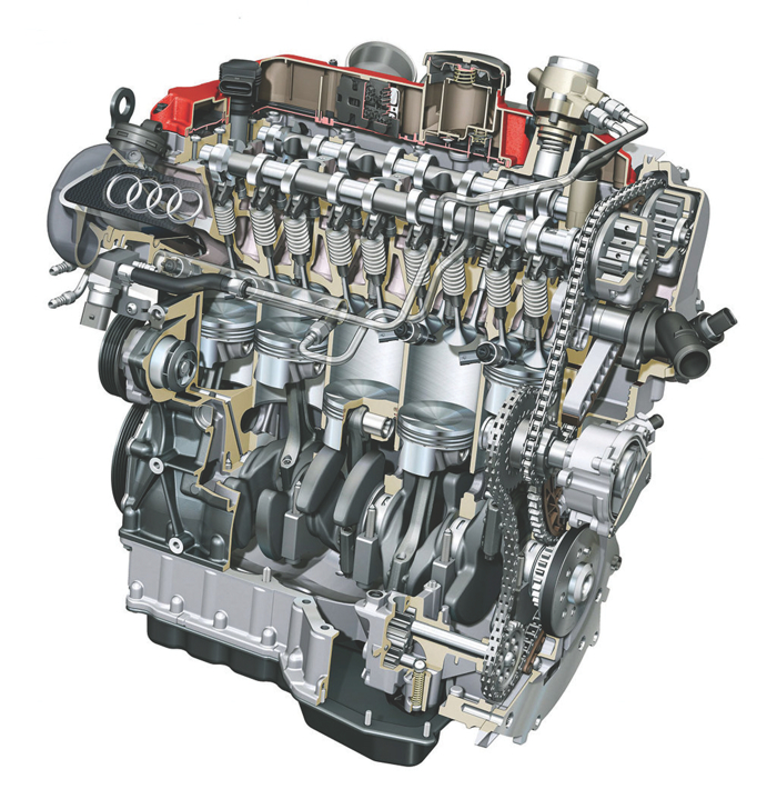
If you look up direct injection carbon deposit problems on the Internet, engines from BMW, Audi and VW always rank the highest. Engines from GM and Ford that have been on the road for at least four years hardly have a carbon deposit complaint. What’s the deal?
Some direct injection engines have bad timing. The modern engine typically has variable valve timing and even cylinder deactivation. The engine management system can control when, how long and, in some cases, how deep the valve goes into the combustion chamber. If an intake valve is dropping into a combustion chamber with combustion byproducts or unburned fuel, the valve might be exposed to the precursors that cause carbon build-up.
Some have blamed the positive crankcase ventilation (PCV) systems for leaving an oily film on the intake valve that is then baked into carbon. Some blame the valve overlap during the intake stroke that eliminates the need for an EGR valve.
The Fix
There are several fixes available to solve carbon build-up problems. The first is preventive maintenance. Scheduled oil changes can keep the camshaft actuators working in optimal condition to control the exposure of the intake valves. Spark plug replacement can reduce the amount of unburned fuel in the combustion chamber that can stick to a valve. Fuel injector cleaning can help injectors maintain the correct spray geometry.
But the number one method for preventing a ¬carbon build-up problem is updating the engine management software. New software can reduce carbon deposits by reducing the exposure of the valves to conditions that cause carbon build-up by adjusting valve and spark timing.
Don’t assume that you will find a TSB saying that a reflash of the ECM will correct a carbon build-up problem because most of the updates will be contained in normal housekeeping that may never say anything about a problem. You may even have to check the OEM’s website to see if the vehicle has the latest version of the software.
Drivability Diagnostics
and Direct Injection
Years ago, all a low-level technician needed to diagnose a fuel problem was a set of “noid lights,” a fuel pressure gauge and maybe a meter. These tools can’t be used on direct injection systems because of higher pressures and changes in the injector location and technology. Voltages from the injector drivers can range from 30-120 volts depending on the system, and pressures can go as high as 2,300 psi. The go-to tool for direct injection will be a scan tool that can look at special direct fuel injection parameters and perform bi-directional tests.
Some of the tests are the same, such as the injector balance and load testing, but more insight is needed into how the placement of the injector and the high-pressure fuel pump play into drivability diagnostics.
Direct Advantages
Despite not offering the “cleaning function” of the fuel and detergent, by directly injecting into the cylinder, the system avoids the inconsistencies of fuel splashing onto the back of an intake valve. Also, fuel droplets are much smaller in a direct injection system than in a port fuel system – so small it’s almost vapor. These smaller droplets help to remove heat from the combustion chamber in order to lower temperatures and use leaner mixtures. Direct injection systems reduce cold start emissions and enter into a closed-loop condition sooner than port fuel injection systems.
With better control of air and fuel, pumping power losses can be managed more efficiently. Throttle angles are also managed more efficiently so that air isn’t fighting the throttle plate.
The pressure differential on the direct injection engine is much lower than on port fuel engines. A small vacuum leak past the throttle body can have larger ramifications for direct injection.
Pressure Diagnostics
You will never find a Schrader valve or port to measure pressure on a direct fuel injection system, even on the low side. If you were able to tap into the low side with an analog gauge, you would see pressures rapidly changing as demands on the engine changed. If you managed to splice an analog gauge into the high-side pump, the needle would be pegged. The splice would eventually leak, and the pressure coming out of the leak would be so great the stream of fuel could cut through skin and bone. This would be followed by a fireball.
Direct injection pressure is measured with sensors, and the signals are used to determine pump speed and/or volume. So, you’ll need a scan tool to look at the pressures.
Most direct injection systems use piezo-resistive pressure sensors on the low side of the system. The silicone chip element generates a measurable electrical voltage when pressure is applied, increasing as pressure increases. The ECM will turn the voltage into a calculated pressure that has a ±2% accuracy. Measuring the values with a scope or meter will not yield any important information, so always look at the value with a scan tool.
High-pressure sensors may use a metallic membrane on a resistance bridge. When pressure is applied, the bridge generates a change in resistance that will cause a change in the applied voltage.
The ECM is supposed to ensure the fuel pump is supplying the correct pressure to the high-pressure pump. The ECM will pulse the low-pressure pump so that the correct pressure is generated. The system typically has a regulator and no return lines. Some systems even have integrated temperature sensors in the lines that are used to calculate the density of the fuel so that the fuel trim can be tuned to the amount of energy in the fuel.
Low-Pressure/Supply Pumps
The low-pressure, in-tank pump is typically controlled by the ECM with a pulse-width modulated voltage signal. Its main responsibility is to provide the correct volume and pressure to the high-pressure pump. With this arrangement, there is no need for a return line.
The supply pump also can activate a limp-home pump if the high-pressure pump fails. If the ECM detects a failure of the high-pressure pump with information from the high-pressure sensor, it will increase the output of the supply pump and the open injector time so that the engine can continue in a restricted power mode.
High-Pressure Pumps
The high-pressure pump on a direct injection engine shares more in common with an ABS modulator pump than mechanically driven fuel pumps.
Mechanical pumps use pressure and other engine-related information to determine output, which is controlled by an actuator, typically on the intake side of the high-pressure pump. When there is no voltage applied to the solenoid, it will revert to the low-pressure setting.
This pump is precision-machined to generate fuel pressure to the rail up to 2,500 psi. Fuel lubricates the internal parts of the pump, and if the fuel system is dry, the pump can be damaged. Debris from a failed filter or pump that makes its way to the high-pressure pump can also cause damage.
The main destroyer of high-pressure fuel pumps is a lack of oil changes. Wear between the camshaft lobes and the high-pressure pump prevents the fuel pump from generating enough piston movement. You should always examine the lobes on the camshaft before installing a new and very expensive high-pressure fuel pump. A lack-of-power complaint may improve, but it will never be completely corrected.
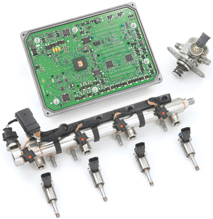
Injectors
With more than 2,000 psi on the backside of an injector, and combustion pressures on the other, more than 12 volts are needed to pulse the injector. Most direct injection systems use a capacitor and voltage inverter to create voltages that can range from 40 to 100 volts, depending on the system. It’s possible to view the output of the driver using an induction clamp.
If the ECM detects a problem, it will shut down the injector and driver for the sake of self-preservation. This is why it may be impossible to observe a faulty injector in operation on some systems.
A direct injector is under a lot of pressure, so leaks can happen. Some leaks may occur when the engine is resting, which will cause severe carbon build-up and a rich fuel reading.
When an injector is not firing, the affected cylinder becomes an air pump that forces large amounts of oxygen past the air/fuel ratio sensor. This can be viewed using a scope. The ECM can match the exhaust pulse to engine timing to determine the faulty cylinder.
Diagnostic Margins
Engineers are building test cylinders with ruby quartz windows and are using the best high-speed cameras in the world to determine the best possible combustion event under different loads. They want to tune the perfect combustion event in which all the fuel is burned and the lowest amount of emissions makes it to the converter. This quest for perfection will become a diagnostic challenge for technicians in the years to come.
For example, a little bit of carbon on an intake valve can cause the air going into the combustion chamber to be turbulent and cause some of the fuel to condense and burn unevenly. Or, a small vacuum leak could cause unmetered air to enter into the combustion chamber. Even a small change like an air filter may throw off the combustion event.
Port fuel injection motors compensated for these issues because they were expected to be somewhat inefficient. They had lower compression ratios and larger catalytic converters.
Now, every little item, from the condition of the spark plugs to the type of fuel used, is essential for a diagnosis. Worn parts and missed maintenance can cut into the diagnostic margins.
Veteran technicians can probably look at the data stream for timing, fuel trim and oxygen sensor values to determine the health of an engine or spot a problem before a vehicle turns on the check engine light. For a direct injection engine, some events you see will not match conventional wisdom. You will be amazed at how lean the system will run, how much ignition timing can change and when the injection event will happen.
Parts-swappers should stay away from direct fuel injection. The parts are expensive and the majority of drivability problems can’t be solved with just one part or procedure. Technicians who look at the entire system and deduce where a problem originated will be ahead of the game.
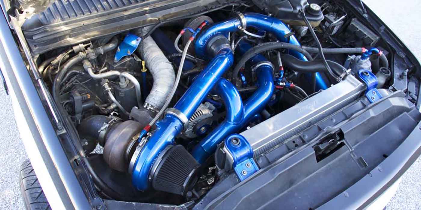
Common Rail Injection
Technological changes for diesel engines may often be viewed as complex, but once they are understood, validate the performance and efficiency benefits we appreciate today.
Common rail injection for mid-size trucks has been around for nearly 15 years. While many owners appreciate the quietness and dependability of their diesel engines, many have no clue as to what changes have taken place to the fuel system in order to not only make their diesel perform, but also be emissions-compliant. For the most part, common rail is simple in design, but can be quite complex thanks to the related parts and sensors that create the orchestra for the system.
The benefits of Common rail are:
Higher injection pressures which produce finer atomization of fuel;
Fuel pressure available “on demand”;
Injection pressures created independent of engine speed;
Multiple injections per cylinder combustion are possible;
Reduction of exhaust emissions;
Reduction of particulate emissions;
Noise reduction;
Fuel efficiency; and
Higher performance.
The diesel fuel system can be divided into three basic circuits consisting of supply, pressure and return. The Common rail system starts with a high-pressure pump, usually manufactured by Bosch, Denso or Delphi. Even though the pumps may vary in design, the basic principle is the same. The pump is engine-mounted and driven from the front or rear gear train of the engine.
The low-pressure circuit consists of the fuel lines from the fuel tank through the fuel filter and to the high pressure pump. Bosch-style pumps have a transfer pump built into the body of the pump housing. Fuel is drawn in from the tank and through the filter to supply the high-pressure pump. For Denso-style pumps, fuel is supplied to the pump, usually from an electric in-line or in-tank pump.
The high-pressure circuit consists of fuel that is pressurized by the high pressure pump. As fuel enters the pump, there are pistons and valves that that make up what is known as pumping chambers where the fuel is pressurized.
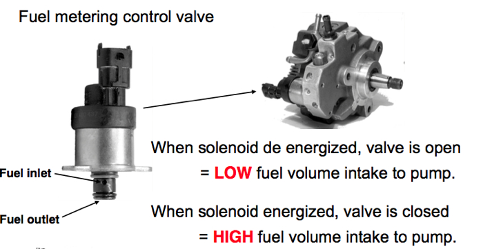
A regulator is placed in the pump to control the amount of fuel that will enter the chamber. Once the fuel is pressurized, it then enters a high-pressure steel tube and is carried from the pump to the “Common Rail.” The pressure generated by the pump can range from 5,000 psi at idle to 23,000 psi and upwards of 28,000 psi on newer systems at wide open throttle.
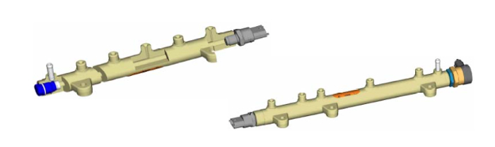
The “Common Rail” (also known as an accumulator) looks like a thick steel log with high-pressure steel lines extending from it to feed the individual cylinder injectors. A fuel pressure sensor on the common rail informs the ECU as to how much pressure is inside the accumulator. The ECU then controls the regulator of the high-pressure pump to obtain the desired amount of pressure for maximum efficiency.
There are advantages to having a regulator that controls intake volume of the high pressure pump: only the required amount of fuel is supplied to the pump to be pressurized. This keeps fuel return at a minimum, which helps reduce fuel temperature. Less load on the pump reduces parasitic load on the engine, which helps to reduce emissions.
In a case where there is too much pressure in the common rail, there are two types of reliefs that can be found depending on the vehicle’s system. One type of relief is known as a mechanical pressure limiter. The limiter is placed at the end of the common rail and consists of a spring-loaded plunger. If excessive pressure is reached in the rail, the valve opens and the fuel is dumped back to the return.
There is also an electric version of this seen in newer systems, known as a fuel rail pressure control valve solenoid. This valve is controlled electronically by the ECU and because of its faster response time is able to more quickly relieve excessive fuel pressure in the common rail.
Next for the high pressure system are the injectors (see photos at the bottom of this page). The injectors are electronically controlled by either a solenoid or piezo actuator and are energized by the PCM with multiple injections per combustion event. This is where we need to take a look at multiple injection events and what they mean.
High-pressure fuel is supplied to the fuel injector from the tubes extending from the common rail (left photo, below). Fuel flows inside the injector to a needle and seat and also to a small chamber above the injector piston through a small, calibrated port.
When the solenoid is energized, the injector valve opens (center photo, below). Fuel pressure is relieved above the injector piston and returns fuel back to the tank via the return system. This creates a pressure difference above and below the injector piston.
Fuel pressure below the injector needle lifts the needle off the seat. High-pressure fuel then enters the nozzle where it is sprayed into the engine cylinder in micro fine droplets (right photo, below). The processes of the injector to perform injection happen at a very fast pace and is usually measured in milliseconds. As mentioned earlier, the injector can perform these events as much as five times per combustion event. Here is how the five injection events take place:
Pilot Injection – This takes place as the piston begins its travel up the cylinder bore shortly after Bottom Dead Center. This injection event allows a small amount of fuel to enter the cylinder to let the fuel and air begin to mix.
Pre-Injection – This is where an amount of fuel is added again to shorten the ignition delay for the main injection. This helps reduce noise or what is known as “fuel knock” when the main injection takes place. This injection cycle also reduces engine vibration along with reduction of NOx (Nitrogen Oxide) gas.
Main Injection – This injection event provides fuel needed for combustion and power.
After Injection – This injection event occurs in a split-second after the main injection. This helps burn any remaining PM (Particulate Matter).
Post Injection – This injection event is used for what is known as “REGEN” or regeneration to clean the DPF (Diesel Particulate Filter).
All of these injection events will take place in approximately 0.4 milliseconds per combustion event.
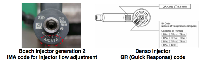
In 2007 and newer vehicles, if there is an injector failure, the replacement of the injector can present a challenge. While the job itself may not be difficult for someone to perform, the ECU on the other hand will need to be programmed with the new calibration code from the replacement injector for the engine to perform correctly. The injectors trim code relates to the flow rate of the injector. The ECU uses this code to correct the injection quantity to compensate for manufacturing tolerances.
This is a basic overview of the common rail injection system. Please keep in mind that all sensors and actuators are controlled and monitored by the ECU. In addition, some sensor and wiring problem issues that lead to poor drivability along with erratic idle or stall may still need to be diagnosed by a qualified technician.