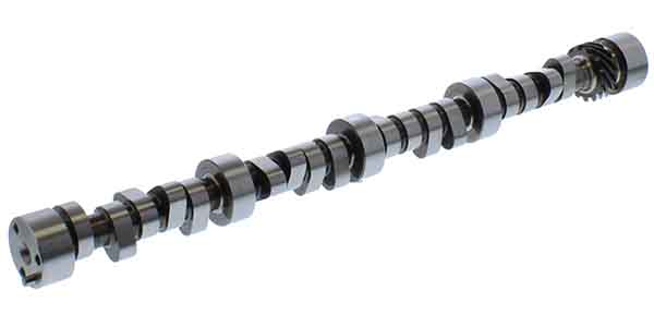
“What camshaft should I use?” How many times have you been asked or heard that question uttered? Why is it so difficult to choose the “correct” camshaft for an engine build? What separates one camshaft design from the other? After all, isn’t it true that a camshaft opens and closes valves? Simple, right? Well let’s delve in and see what we can learn about the operation and selection of the “best” camshaft.
Proper camshaft selection allows the maximum amount of air/fuel mixture into an engine for a given application. The amount of fuel that can be used, then removed efficiently, (volumetric efficiency VE), will not only dictate engine power but also the entire engine package selected for the build. After all, the camshaft design affects valve timing, compression and the engine’s ability to breathe. From pistons to manifolds, valve grind, piston pin offset, rod length, etc. Once the camshaft has been tabbed correctly for the application, the rest of the build can focus off that selection.
What won’t be provided here is a “sure-fire can’t miss” camshaft selection formula. It simply doesn’t exist. The list of variables is far too great. Proper camshaft selection is a combination of first and foremost, your experience coupled with the determined usage; engine displacement, compression ratio, fuel system carbureted or injected, RPM range power desired, transmission type/converter stall speed, vehicle weight, final gear ratio, tire height, cylinder head and valves, head flow, manifolds, rocker arm ratios, aspiration and emissions test passage if necessary.
Too often the camshaft grind is selected based off of numbers that “look” great on the packaging but have little to no benefit. Think bigger is always better? Not always so in the case of camshaft selection. The addition of 25 base horsepower on a camshaft install is great, provided it enhances the application. However, if the build is for a street performance engine, adding 25 horsepower above 6,500 RPM might mean utilization of the “added” horsepower is difficult.
Let’s begin the journey now and see what we can learn.
Camshaft Basics
It is true that the camshaft is responsible for opening and closing valves. The critical aspect is the timing of these events. The correct camshaft selection will match valve operation to pressure differentiations and airflow inertia for a selected RPM range to produce maximum volumetric efficiency (VE).
Before delving in too deep it should be understood that a bevy of internal engine parameters affect cam timing. These criteria include-engine bore and stroke, connecting rod length, pin offset, desired operating RPM, static and dynamic compression, intake and exhaust flow as well as cylinder head flow. If our choices are correct the camshaft selection will be successful. If not, well let’s hope this article helps to prevent any such dilemma.
Let’s start with a quick rundown of some terminology.
Duration- is simply the number of crankshaft degrees that a valve is off its seat (held open). An air/fuel charge enters or exhaust gases exit the cylinder whenever a valve is open. In general the longer a valve is open the higher the RPM an engine can rev. The higher the duration the longer the valves are held open affecting both the power band and driveability. Longer duration (higher number) improves top end power with an expected reduction in low-end torque.
Lower duration boosts low-end torque which results in better idle quality but sacrifices top-end power. Short duration cams also limit valve lift due to rate-of-lift limits of the lifter. Roller cams offer an improvement here over hydraulic grinds, by allowing higher rates of lift with short duration.
Comparing camshafts can be tricky as duration numbers are generally supplied by two figures; advertised and .050 inch. Advertised is generally between .003 inch and .006 inch off the seat. SAE designates .006 inch as the official figure. What occurs before .003 inch is largely considered irrelevant. For camshaft comparison the .050 inch (crankshaft degrees) starting and ending figure is typically used. The .050 inch figure constitutes generally how the cam will operate.
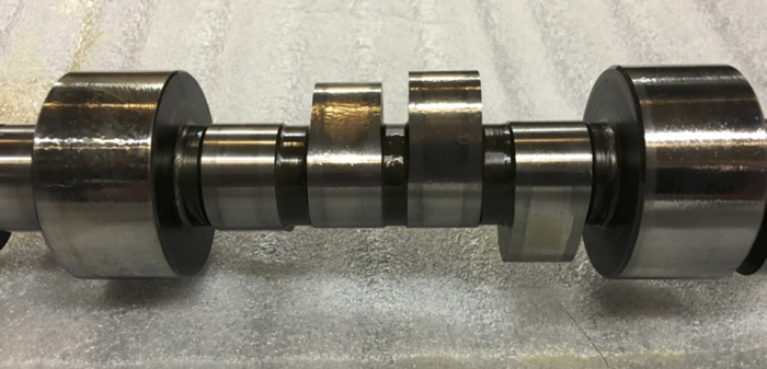
Lift-easily the best understood specification of camshaft design. Maximum valve lift is calculated by multiplying lobe height at its highest from the base circle of the lobe, times rocker arm ratio. The rocker arm ratio multiplies (increases) the effective lift of the camshaft lobes. For example, a 0.310” lobe lift cam yields 0.496” of valve lift when using a 1.6 ratio rocker arm.
Peak lift on most engine builds are constrained by engine design;
A.To maximize valve clearance the piston crown can be modified. Hence, a concession must be made between the amount of valve lift that can be selected without being detrimental to piston design.
B.Short duration high lift designs also constrain valve lift by cause of acceleration needed to obtain high lift. As RPM increases, peak lift is reduced for a given valve lift duration.
Typically more lift increases power. Increasing lift, while not altering duration will boost power without changing the power band.
If peak lift is too low airflow will be restricted into and out of the engine reducing power. This is known as throttling the engine. To achieve maximum power typically a camshaft with as much lift as possible should be chosen for the airflow capable of the cylinder head and manifolds. Maximum possible lift can negatively alter low-to-mid range performance.
A lower intake valve lift increases air charge momentum passed the open valve. The increased velocity leads to enhanced fuel mixing and combustion. For added torque at a selected RPM keep the lift as low as possible without restricting the air charge.
Ordinarily peak valve lift selection is not governed by partial load conditions. Deriving valve lift for this application would in all probability reduce the engine power output. However to increase fuel economy during low-to-mid operation restricting the valve opening via valve lift is an option. Curtailing airflow past the intake valve diminishes the engines need to reduce airflow via the throttle plate reducing pumping losses.
To find which lift is best for your build find the maximum cylinder head flow point and match the lift to that range. Superfluous lift can cause engine reliability issues. High lift camshafts place an inordinate amount of stress on engines valvetrain and valve seats. Insufficient lift results in poor performance and failure to achieve maximum horsepower. Accordingly a concession is necessary when selecting peak valve lift. Your decision is entirely dependent on intended RPM and load the engine will be operating in.
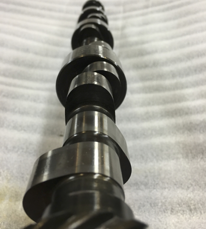
Lobe centerline (LC)- is the peak lift point of the cam lobe in crankshaft degrees. Intake lobe centerline is ATDC and exhaust lobe centerline is BTDC. Symmetrical cam (both sides of the lobe are exactly the same) centerline therefore is the halfway point between intake and exhaust centerlines. An asymmetrical cam may use different durations on the opening and closing side of a lobe. This will affect the centerline as it may not be dead center. Asymmetrical refers to a camshaft lobe profile where the opening and closing ramps are not exactly the same. The reason some camshafts are this way is to try to achieve an opening ramp profile that has a high velocity and a closing ramp profile that has a slower velocity. In this way the valve can be set down more “gently” than the rate at which it was first opened. The difference if present is minuscule
Lobe Separation Angle (LSA) or Lobe Centerline Angle (LCA)- is the only camshaft specification rated in cam degrees, not crankshaft degrees. Lobe separation is the angle in camshaft degrees between the maximum lift points of the intake and exhaust valves. LSA is the result of the placement of the intake and exhaust lobes on the camshaft and cannot be changed unless the cam is reground. This is usually calculated by dividing the sum of the intake centerline and the exhaust centerline by two.
This measurement is another way of expressing valve overlap, the amount of time that both valves are open on the same cylinder; as well valve opening and closing points and lobe centerline. In a nutshell the engine responds to valve timing events. This is the reason that Lobe Separation Angle alters valve overlap as it also changes the four valve timing events of a camshaft. Lobe separation affects valve overlap which in turn affects the power curve of the engine, idle quality and vacuum.
Valve Overlap- the time when both valves are open as the piston travels in the bore. Overlap begins as the piston approaches TDC on the exhaust stroke and continues until just after TDC. The correct overlap is essential for optimal performance encompassing endless hours of engineering design. When both valves are open simultaneously a drop in cylinder pressure will occur. Overlap is most easily understood as the ability of intake and exhaust flows to affect each other due to pressure waves that vary with load and engine RPM. All in all valve overlap is quite balanced around TDC on most engines. Piston motion has the greatest effect on airflow the further from TDC that valve overlap exists.
Theory behind valve overlap; since the intake valve is open slightly departing exhaust gas flow creates pressure differential (vacuum) that aids in pulling fresh air/fuel mixture into the cylinder without any of the intake charge passing into the exhaust system. The exiting exhaust gas at TDC that is replaced directly by the intake charge would exceed that which is normally drawn into the cylinder by piston travel alone. Think poor man’s turbocharger/supercharger.
Overlap trails only duration in its ability to produce power. Additional horsepower increases with the appropriate amount of overlap and can easily exceed output from a relatively identical camshaft with a wider lobe separation. Additional duration, increasing overlap by opening the intake valve earlier and closing the exhaust valve later, is commonly found on performance camshafts. Altering the intake valve opening point is typically the most dynamic modified cam timing event followed by exhaust valve closure. Exhaust valve closure is primarily used to regulate the amount of overlap.
As with almost anything engine performance related however, a trade-off exists. Adding overlap can result in poor idle quality (low vacuum), elevated emissions, and poor throttle response until RPM overcomes intake and exhaust reversion.
Increased overlap is beneficial at higher speeds and loads due to exhaust pressure waves drawing in the intake charge while both valves are open. As the piston travels from BDC pushing exhaust gases from the cylinder the intake valve begins to open before BTDC. Application dependent this process may start as early as 50°BTDC on a race application compared to a street vehicle which can be as late as 3° to 5° BTDC. Exhaust valve closure operates in a comparable range ATDC. Adding the intake BTDC to the exhaust ATDC closing events results in crankshaft degrees of overlap.
Typical overlap for a given application as follows; trucks/good mileage towing 10°-35°, daily driven low rpm performance 30°-55°, hot street performance 50°-75, bracket/oval track racing 70°-95°, dragster/comp eliminator engines 90°-115°. Large overlap at lower speeds results in poor emissions and idle quality as the mixture flows directly into the exhaust never burning. High overlap also results in an EGR effect that although beneficial for emissions at part load, reduces power under full load.
The Four Stroke Cycle
Ok so now we need to understand the terminology and design aspects of the camshaft. For starters however a review of the 4 stroke cycle is in order… yea I know, you’re saying to yourself really? Isn’t that the same as reading instructions, who does that? It’s even more simplistic than camshaft operation. After all what can be so hard about Suck-Squeeze-Bang-Blow? Ah that’s what we are aiming to expand upon here; valve timing in relation to piston location in the bore. How to manipulate the timing of these events to provide what the customer and/or engine builder is hoping to achieve for the given application. The theory well….
1. Intake stroke- The piston is at TDC from zero velocity. As the piston begins moving down the cylinder from TDC the intake valve opens and the exhaust valve is partially open. As the piston descends it picks up speed and the exhaust valve fully closes. With the valve opening air and fuel begin to fill the cylinder. It is commonplace to assume that the vacuum created here is solely responsible for the cylinder filling to reach maximum volumetric efficiency. This however is only partially true. The piston reaching its maximum velocity (approximately 70°-80° ATDC) provides the greatest pressure difference between atmospheric pressure and cylinder pressure. Piston velocity derives from stroke, rod length, piston pin offset and RPM. The greater the velocity, the more air we can draw into the engine. As the piston travels down the cylinder the exhaust valve fully closes while the intake valve, which is fully open, begins to close as piston reaches BDC. Why keep the intake valve open slightly after BDC? Momentum from the incoming intake charge continues to fill the cylinder even though the piston has slowed at BDC. Enhancing Volumetric Efficiency.
2. Compression stroke- The piston reaches BDC and two events are simultaneously occurring- the intake valve is almost closed and the piston speed slows greatly. The intake valve closes fully after BDC. Momentum from the incoming intake charge continues to fill the cylinder even though the piston has slowed at BDC. The piston then begins the journey back to TDC on the compression stroke squeezing the air fuel mixture to an elevated pressure/temperature that allows the spark plug to ignite and burn the mixture. This event is critical as the burn needs to be controlled, not an explosion (detonation). End result of detonation- engine damage, usually melted ring lands. Proper controlled burning returns the piston at maximum velocity to BDC.
3. Power stroke- The piston is at TDC with both valves closed, the spark plug has fired. The expanding gases from the ignition event of the compressed air/fuel mixture forces the piston back down the bore. As the gases expand cooling also begins. The exhaust valve begins to open before the piston has reached BDC. Most of the gas pressure from combustion contained in the cylinder is depleted between 45° and 90° ATDC. When the crankpin reaches 90° ATDC most of the power has been recovered and cylinder pressures are low. Opening the exhaust valve before the piston reaches BDC allows the excess pressure in the cylinder to be expelled just before the piston reaches the bottom of the stroke. Opening of the exhaust valve during the power stroke aids in reducing cylinder pressure and pumping losses. The term “Blow Down” is used to describe this action.
4. Exhaust stroke- The exhaust valve is opening fairly rapidly as the piston begins its ascent. As piston velocity increases the exhaust valve needs to be fully open to reduce resistance (pumping losses) which robs power and fuel economy. Exhaust valve closure is delayed until after the piston has reached TDC and begins its descent to take advantage of the exhaust gas velocity and increased cylinder scavenging. Delaying exhaust valve closure and beginning to open the intake valve on the exhaust stroke also aids in reducing pumping losses. This increases cylinder fill during the intake stroke due to the negative pressure (vacuum) in the cylinder via a process known as scavenging. The vacuum created allows more air/fuel mixture to fill the cylinder as well as ensuring the exhaust gases are purged efficiently.
Editor’s note: This article is the first in a three-part series. Look for more camshaft design information in upcoming Engine Builder issues.
Acknowledgements
Thanks to Matt Dickmeyer, David Vizard and Gary Goms for provided interviews or reference material; as well as Comp Cams, Lunati Cams and Crane Cams for online resources.

