In the past decade, turbochargers have found their way onto more engines in cars and light trucks than ever before. By 2021, predictions by some experts cite turbocharged vehicles will reach up to 38 percent of all new vehicles sold in the U.S. Once thought of as only a means to increase performance on exotic sports cars, forced induction is now carrying the torch for reduced emissions and improved fuel economy. By increasing the use of turbochargers on smaller displacement engines, manufacturers hope to meet and reduce increasingly demanding CO2 emissions and fuel economy standards that are changing the way engines are built.
Modern engine design technology continues to trend on downsizing and boosted power plants. Manufacturers must meet or exceed standards set in place by the EPA for new vehicles sold in the U.S. The requirements for the 2025 model year nearly double fuel efficiency to 54.5 mpg, while cutting greenhouse gas emissions in half, all without sacrificing performance.
When compared to a normally aspirated engine with the exact power output, the fuel consumption of a turbocharged engine is considerably lower due to an increase in the power-to-weight ratio. By using a portion of the normally wasted exhaust energy to improve the engine’s efficiency, displacement can be smaller, therefore, reducing thermal and frictional losses.
Turbocharged engines also thrive at high altitudes. Naturally, aspirated engines suffer a substantial drop off in power due to lower air pressures at high elevations. Turbochargers, however, suffer virtually no noticeable loss of power. Lower air pressures improve turbine efficiency, a result of the pressure difference between the reduced pressures at the turbine outlet (less atmospheric pressure) versus the higher pressure upstream of the turbine (exhaust pressure).
Design and Operation
The basic operation of a turbocharger has not changed since its inception. The expansion of normally wasted exhaust gases drives a turbine. Mounted on the same shaft as the turbine, the compressor draws in, and pre-compresses the same volume of air as it would inhale without a turbocharger, but at a much higher pressure and mass. Increasing the air mass allows more fuel to be burnt, increasing the engine’s power output.
Due to the use of smaller displacement engines, full boost pressure must be available at low engine speeds to produce the necessary power when needed. Boost, therefore, must be controlled on the turbine side of the system to provide the seamless power transitions required.
Boost Control
The idea of a turbocharger is to force more air into the cylinders increasing volumetric efficiency which increases the engine’s ability to produce power. There needs to be a way to control boost pressure, however, since the turbocharger cannot self-regulate its output. After all, a turbocharger uses the expansion of exhaust gases and their heat to create boost. So, increasing boost pressure continues to build more boost, further increasing the exhaust air temperature and pressure, which, if left unchecked, would continue this vicious cycle until a catastrophic failure of the turbocharger, engine, or both occurred. Enter the wastegate, or bypass valve to control the system.
A wastegate is used to control maximum boost, and blow-off valves/bypass valves are used to relieve boost pressure on deceleration. Wastegates redirect the exhaust gases around the turbine wheel to bypass, or maintain flow to the turbo. The wastegate utilizes a diaphragm attached to an actuator rod that opens and closes a valve controlling the exhaust gas flow. Gasoline OEM engines typically use a wastegate that is integrated into the turbocharger saving space for installation purposes. Aftermarket and performance turbochargers can use an external design that offers increased performance through the utilization of a larger diaphragm. Control of the wastegate is referenced by the pressure created from the turbocharger. This pressure, known as the wastegate actuator signal, is picked up at either the intake manifold or turbo compressor discharge and carried to the wastegate actuator by a hose. When the pressure overcomes the internal spring pressure of the wastegate, boost pressure is released back into either the intercooler or exhaust system, depending on the system used. Some aftermarket systems will release the pressure to the atmosphere.
The bypass or pressure relief valves, also known as a ‘Blow Off Valve’ (BOV) or surge valve, release pressure when the throttle snaps closed during deceleration or when shifting. The unnecessary boost pressure is directed back to the compressor inlet after the MAF sensor on OEM vehicles and generally released to the atmosphere on performance and aftermarket designs. Releasing the pressure to atmosphere provides the familiar “WHOOSH” sound heard so often. Engine vacuum, not pressure, controls the bypass and pressure relief valves. Vacuum is assisted by boost pressure acting on the bottom of the valve, while vacuum pulls against spring tension in the diaphragm to open it.
Electronically Controlled Pressure
Late model OEM vehicles now control boost pressure and bypass pressure electronically via the PCM. Electronic controls, when compared to purely pneumatic control that only operate as a full-load pressure limiter, allows optimal part-load boost pressure adjustments. Electronic control offers better, more precise control that is infinitely variable boost increasing efficiency and lowering emissions. The PCM uses multiple sensor inputs to monitor the pressures. Typical inputs include- engine load sensors Manifold Absolute Pressure (MAP) and Mass Air Flow Sensor (MAF) if equipped. For spark timing and boost control at least one Knock Sensor (KS), some engines use multiple sensors, especially V-engines, Throttle Position (TP), Throttle Inlet Pressure (TIP), and temperature sensors Engine Coolant (ECT) and Ambient Air Temperature (IAT).
Current wastegate control uses one of two methods, either a wastegate solenoid that redirects the boost pressure signal (actuator signal) or an electric motor that drives the wastegate actuator rod. The wastegate solenoid is duty-cycle controlled by the PCM offering constantly variable, optimal control. Electronically controlling the wastegate, and not relying solely on mechanical spring pressure, prevents the wastegate from cracking open prematurely as boost pressure rises, reducing boost. By controlling the actuator accurately, the turbo can build ideally desired boost levels, without fear of engine or turbo damage.
An electronically controlled wastegate motor takes boost control to another level. Operating independently of boost pressure (mechanical/pneumatic wastegate), or boost pressure reference (PCM controlled wastegate) the speed, accuracy, increases significantly. Furthermore, using an electric motor allows wastegate use for additional tasks, not typically associated with a turbocharger. Primarily the electronic motor offers infinite control of boost and increases maximum boost pressure with better control of the wastegate, holding it closed until needed. Additionally, the wastegate is used to reduce pumping losses and emissions. By opening the wastegate when boost is not necessary, the turbine is bypassed, removing the restriction of exhaust flow, reducing pumping losses, increasing fuel economy. Finally, by opening the wastegate during a cold start, catalytic converter light-off times are decreased, reducing emissions.
Bypass or surge valves are also electronically controlled by the PCM. A solenoid is activated controlling vacuum to the valve. The bypass solenoid is usually an on/off solenoid only, not duty-cycle controlled like the wastegate. When activated, the solenoid is simply turned controlling vacuum to the valve. Opening the solenoid applies vacuum to the bypass valve ‘dumping’ turbo boost.
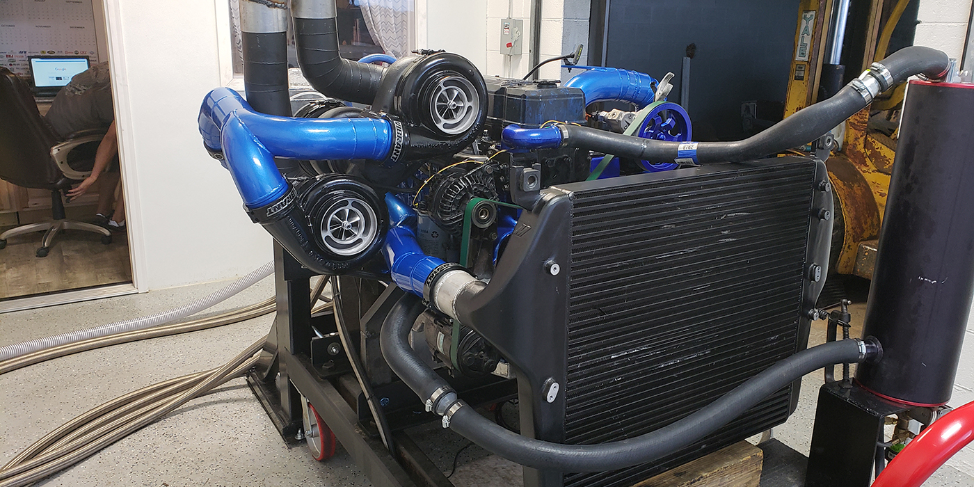
Additionally, some turbochargers do not use a wastegate. Boost is controlled by moving vanes on the turbine side of the turbo. A series of vanes are positioned on a unison ring that rotates based on control by an actuator, opening and closing the vanes, thereby adjusting the amount of exhaust energy reaching the turbine wheel. During acceleration and at low speeds, the vane gap is tightened increasing low-speed torque and pressure. As vehicle speed increases, the load diminishes; the vanes gradually open until the desired boost level is reached. Adjusting the vanes not only offers minimal turbo lag and optimal boost levels regardless of the load level, but it also reduces fuel consumption by opening the vanes when boost is not required. During acceleration, the vanes are closed increasing boost levels.
The Boost-Compression Relationship
While the basics of turbocharger operation have not changed; the technology used to control turbocharger output, and the engine construction needed to support the increased cylinder pressures achieved during boost reliably, have changed tremendously.
It was learned long ago that the higher the compression ratio, the more torque an engine produces. Increasing the compression ratio increases the engine’s thermal efficiency. In other words, the engine generates more heat as horsepower than it sends packing out of the exhaust as wasted heat. Forced induction increases the effective compression ratio of an engine by adding more air into the cylinder. As more air (boost) is added the effective compression ratio continues to increase. Although the mechanical compression ratio remains unchanged, air and fuel entering the cylinder are already at a higher pressure (from the boost) which raises overall cylinder pressure. Boost pressures of 6 to 8 psi force approximately 50 percent more air into the engine.
Gone are the days of low compression forced induction engines. Improved combustion chamber designs, coupled with a better understanding of how to control the burning of the air/fuel mixture in the combustion chamber, allowing an increase in compression ratios. Compression ratios of 12.5:1 are available on Modern Gasoline Direct Injection (GDI) turbocharged engines. GDI engines require considerably higher fuel pressures for injecting the fuel into the airstream of the combustion chamber during the compression stroke. The fuel, therefore, atomizes much more efficiently than a port fuel injected vehicle, optimizing the swirl effect while improving combustion chamber cooling; and allowing for the higher compression ratios, and efficiency.
Compression ratios still need to be reduced slightly in both normally aspirated, or GDI engines, due to the effects of boost on the relative compression ratio. The drop in GDI turbo equipped engines is marginal. Even naturally aspirated engines can now have compression ratios over 10.0:1 when using a turbo. Increased compression ratios are also a result of the PCMs ability to prevent detonation, by adjusting spark timing advance individually for each cylinder, maximizing power output without engine damage.
The increase in compression doesn’t just apply to OEM engines. Some four-cylinder strip turbocharged engines can top out at a compression ratio of 11.5:1 or more when running alcohol or E85. Even the average high-performance street or strip turbo four-bangers are running a compression ratio of 9.5:1 to 10.0:1, far superior to the ‘good old days’ when 7.0:1 was considered stellar. Plugging in the old theory that a change in the compression ratio up or down by 1 point, has a net effect change in power by approximately 4.3 percent, it is evident why today’s engines are much more efficient in producing power.
Forced Induction Engine Requirements
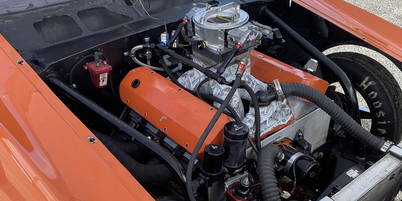
So what does all this mean to the engine builder? As discussed earlier, higher boost equates to higher compression ratios. The increase in effective compression, caused by boost pressure, exceeds the designed mechanical compression ratio. Forced induction requires the use of more robust internal components.
Due to the significant increase that boost provides on effective compression, the first internal engine alteration is typically mechanical compression ratio as compared to a normally aspirated engine.
Engine Modifications to Consider
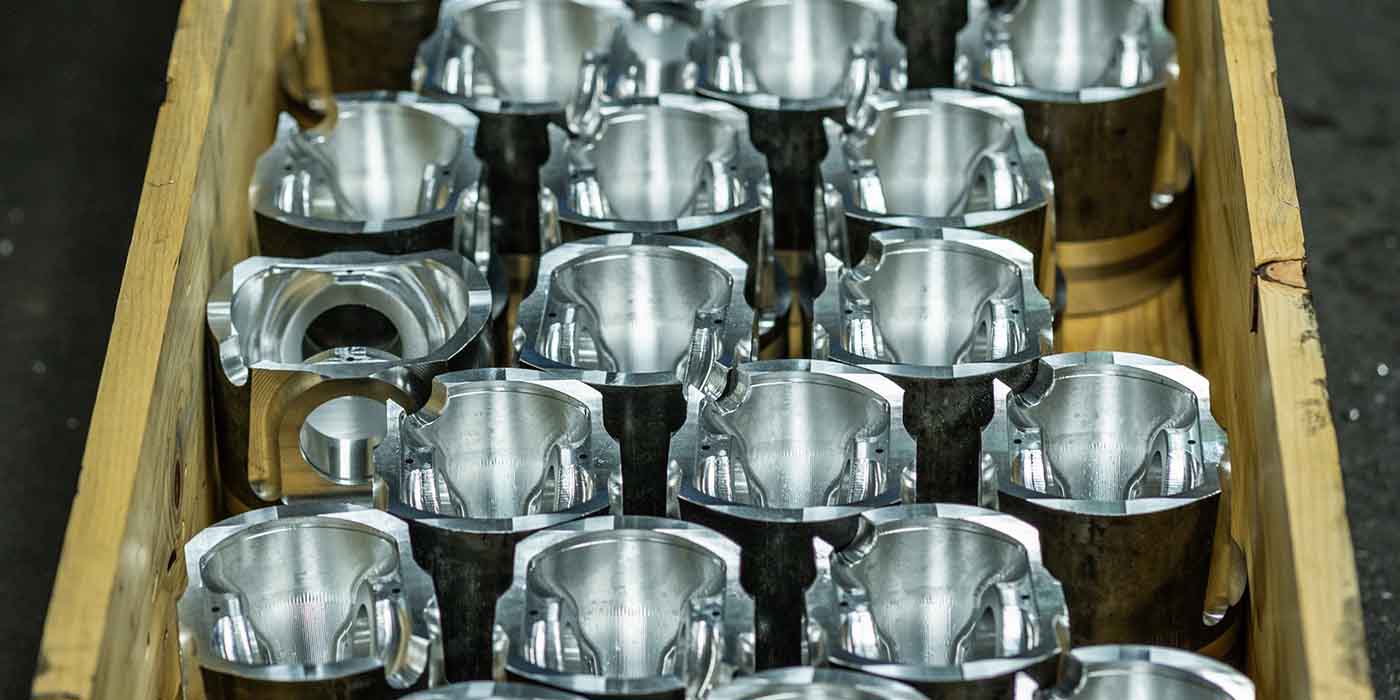
• Forged or billet pistons due to elevated combustion pressures and temperature;
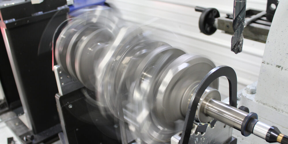
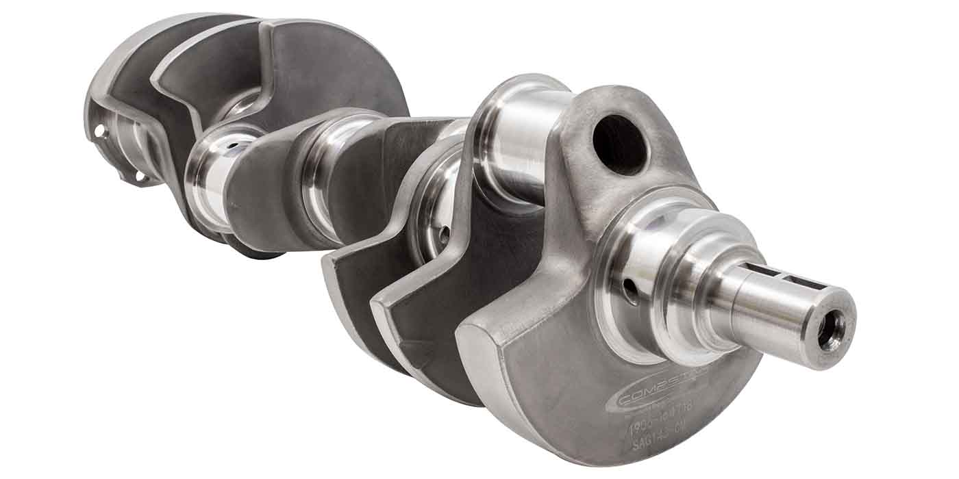
• Forged steel crankshaft due increased cylinder pressures and on belt driven superchargers, from the added strain on the front of the crankshaft by the drive belt;
• Crankshaft may include induction heat-treated fillets and cross-drilled chamfered oil passages;
• Connecting rods of forged steel or powdered metal using H- or I-beam construction for added strength, with high strength bolts and nuts;
• Piston oil qquirters to control piston temperature by directing a stream of oil to the underside of the piston;
•
Cams may use high lift for more
airflow while maintaining intake timing events as close to the same as for a non-forced induction engine;
• Reinforced, higher strength block material, main bearing caps and bolts (4 or 6 bolt main caps);
• Stiffened oil pan to improve powertrain rigidity and reduce vibration;
• Heavier valve springs are required to keep the intake valve closed against boosted pressure. When boost begins to exceed 7 to 8 pounds, it begins to open the closed intake valve;
• Use stainless steel intake valves and sodium-filled exhaust valves to promote cooling;
• Hardened valve seat material on the exhaust valve(s) for increased temperature robustness;
• Pressure resistant head gasket construction;
• Stronger top rings as a result of increased cylinder pressures; including ductile iron, carbon steel (found in many late model OEM engines), and stainless steel, which contains a high percentage of chromium, and hardened or chromium nitride coated;
• May incorporate lightweight cast aluminum, which reduces reciprocating mass inside the engine enhancing efficiency; and/or
• Expanded ring end gap, due to increased temperatures, the piston may expand, closing the gap. Increasing top ring gap by an industry standard of about 0.006˝ per inch of bore diameter.
How to Prevent Turbocharger Failures
Well, you’ve gone ahead and installed a shiny new turbocharger as part of an engine rebuild. Within a few months, the turbocharger failed, and the customer is looking for someone other than themselves to pay for it. What next?
The following are tips from OEM and aftermarket turbocharger companies on how to prevent failure and determine the cause of their failure. Ninety percent of all turbocharger failures are the result of improper installation, use, or maintenance. Due to extremely tight tolerances and high operating speeds, following the proper guidelines for maintenance and service is critical.
Turbochargers are designed to last the lifetime of the engine. They do not require additional special maintenance above and beyond what is required for the engine. To ensure a successful installation following the engine or turbo manufacturer’s recommendations for limited periodic checks:
• Oil change intervals
• Oil filter system maintenance
• Oil pressure control
• Air filter system maintenance
The majority of turbocharger faults are related to a lack of oil/lubrication including sludge buildup, contamination and coking, or foreign object ingestion and over-speeding:
• Sluggish or seized turbocharger as a result of oil breakdown and deterioration causing excessive bearing clearances from low oil level, contaminated oil or oil coking from overheating;
•Damaged blade caused by contamination from dirt or other particles entering the turbine or compressor housing;
•Dirt or carbon in the engine oil
Inadequate oil supply, oil pressure or filter system fault;
•Reduced power or boost from a gas leak or blocked intercooler restricting air flow
• High exhaust gas temperatures, ignition or fuel injection system fault, gasoline or diesel engines;
•Whistling from an air or exhaust leak, or restricted catalytic converter. On diesel engines a plugged Diesel Particulate Filter (DPF) or Diesel Oxidation Catalyst (DOC) can cause a restriction;
• If a DPF is restricted, perform a manual regeneration procedure using the appropriate scan tool after replacing the turbocharger. Excessive backpressure will increase exhaust gas temperatures shortening the turbos lifespan. If the DPF remains plugged or the DOC is restricted replacement is required.
Tuners, particularly in diesel applications, often overfuel the engine resulting in excessive carbon and heavy soot to develop. Over time these deposits can cause sticking and bearing damage. Failure of the air filter to seal correctly or installing a non-approved filter or air intake to cram extra air into the turbo allows erosion (dusting) of the leading edge of the compressor vanes reducing boost. Cracks in the charge air cooler (intercooler) or piping will also result in compressor erosion.
It’s All About the Oil
Inadequate lubrication is considered one of, if not the most frequent cause of turbocharger failure. Failed turbochargers typically must be shipped back to the manufacturer for inspection to determine the cause of failure before issuing a credit to the installer, or customer, states Larry Ireland, Bearing Coordinator for Mahle Aftermarket Turbochargers. Manufacturers employ highly experienced turbocharger forensic specialists, to disassemble and dissect the failed turbo, searching for the clues responsible for its untimely demise.
Before unleashing the boost building beast onto the world reviewing normal maintenance services with the customer will benefit everyone involved- especially in the case of severe duty use. Oil is the lifeblood of the turbocharger, states Larry, lubricating and cooling the bearings of the turbo that can spin at speeds exceeding 250,000 to 300,000 rpm. Proper maintenance intervals, a clean working environment, and using the appropriate oil viscosity and grade are the most important tasks in extending a turbochargers service life to match that of the engine. While engine crankshafts average about 2,000 rpm at highway speeds, turbocharger shafts speeds can reach up to 200,000 rpm. Oil temperatures in a turbocharger can easily exceed 400 degrees Fahrenheit or about twice the average temperature of non-turbo engines, illustrating the need for using only the recommended oil. Increasingly high temperatures can cause engine oil to decompose, resulting in engine deposits and diminished performance.
Inform the customer to avoid repeated short trips that fail to bring the engine to normal operating temperature. Moisture and combustion byproducts collect in the oil turning into a light acid that attacks the turbos bearings and cross shaft. Also stress the importance of allowing the engine to return to idle for a few minutes after heavy use for a few minutes to allow the oil and turbocharger to cool before shutting off. Also never rev the engine as the key is being shut off.
Controlling Turbocharger Temperatures
Heat is one of the worst enemies of a turbocharger, and if left unchecked, can cause overheating, bearing failure and oil coking. OEM late model vehicles may utilize a separate cooling system for the turbocharger center housing and intercooler. These systems typically have a separate radiator, electric water pump, and reservoir. The ECM controls the water pump speed based on sensor inputs to achieve the desired coolant flow rate. Dependent on the manufacturer, the electric pump may be run after the engine is shut down to remove residual heat.
Other OEM applications may use a thermal siphoning condition after the engine is turned off, and the coolant pump is not circulating coolant, to cool the bearings. Heat accomplishes this from the bearings heats the coolant, forcing enough coolant to circulate throughout the system which cools the bearing.
Manufacturers of turbochargers both OEM and aftermarket may offer recommendations to take after driving. The vehicle may be required to run at idle for a set period before shutting off to ensure coolant and oil flow over the bearing after either normal city driving or high demand operation to prevent turbocharging overheating. Always refer to manufacturer recommendations
Bringing it All Together
Due to the high-precision manufacturing processes required to produce turbochargers on the OEM or aftermarket replacement level, such as the enhanced OEM offering by the engineers at Mahle Aftermarket Turbochargers, intrusive manual inspections of the turbocharger should only be performed by qualified personnel.
If the engine fails to operate properly, do not automatically assume the turbocharger is at fault. As Larry stated, a large number of correctly functioning turbochargers are replaced for concerns that instead, are the result of an engine failure. Use the guidelines presented here, to help prevent a costly mistake, possibly alienating a customer. The addition electronic boost and bypass controls, along with the increased use of variable geometry, twin scroll or dual turbochargers, continue to complicate diagnosis. Establishing connections with an ace driveability tech will benefit you and your shop. Turbochargers and their control systems are constantly changing and evolving as advancements in technology continue. The ‘pressure’ is building, technology is showing no signs of slowing, so sit down, strap in, put the throttle on the floor and enjoy the ride! ν
Thank you to the following for assistance and information used in this article: Larry Ireland, Turbocharger and Bearings Coordinator III, MAHLE Aftermarket Inc.; Honeywell Garret Turbochargers; Borg Warner Turbo Systems.