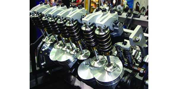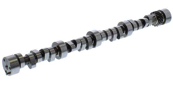
A theory prevails in which a cam lobe that opens to maximum lift and closes instantaneously is quintessential for maximum power and torque operation. Two problems exist with this premise. First, it’s highly impractical due to current technology. Second, this theory discounts a fundamental dilemma that air has momentum, and this must be utilized to achieve maximum power output.
Thus the logic behind opening the intake valve before TDC to increase the air/fuel charge with as nominal a restriction as possible. Ditto for exhaust valve operation.
During the first few degrees (up to 20°) of crankpin movement there is scarcely any piston movement due to the crankshaft moving in a circular motion compared to the linear motion of the piston. Therefore piston speed is not constant; rather more along the lines of a sine wave. Where it accelerates from TDC before slowing near BDC or in reverse from BDC to TDC slowing before changing directions. Opening a valve instaneously while the piston is slowing, results in a reversal of airflow bringing port velocities to a halt; increasing turbulence in the air/fuel or exhaust systems. How do we achieve our goal then?
Exhaust Valve Closing
Exhaust valve closing (EVC) defines overlap which in turn determines the amount of residual exhaust gases remaining in the cylinder at the start of the intake stroke. The presence of residual exhaust gas in the cylinder during combustion is known as Exhaust Gas Recirculation (EGR). The combination of EVC and IVO timing contribute to EGR by either retaining exhaust gases in the cylinder or reintroducing them into the air fuel mixture. Late valve closing can result in reversion, excessive scavenging or reduction of intake cylinder charge fill. Proper operation of the entire exhaust system is paramount to camshaft operation regardless of what decisions we make during our selection.
Most exhaust gases are discharged during the blow down cycle with the exhaust valve open. Exhaust valve closing is critical to prevent detrimental results as well as enhancing engine operation. Closing of the exhaust valve correctly achieves two desired results; the complete removal of exhaust gases and using the gases inertia to begin and assist the intake charge without dilution.
Full load operation prefers the minimum amount of exhaust gas retained. Less exhaust gas allows us to cram the maximum air/fuel charge into the cylinder. To achieve; closing the exhaust valve at or soon after TDC utilizing piston speed and the pressure differential of the cylinder to intake. Optimal EVC timing becomes very significant with pressure waves in the exhaust. Pressure waves influence gases being drawn into or pushed from the cylinder. These waves vary with engine RPM so what is optimal at one speed is detrimental at others.
The addition of EGR to a cylinder slows the combustion process. Operating at low-to-mid load/RPM, by retaining exhaust gas in the cylinder, the amount of air/fuel charge is diminished, thereby reducing RPM. At the same time, this allows the throttle plate to be open farther for the same RPM which reduces pumping losses and increases fuel economy in a street engine. If we continue to move EVC further after TDC the effect of EGR is increased, diminishing emissions up to the point where combustion becomes unstable. Lower RPM and loads are more susceptible to EGR than high load conditions. This is due to a reduction in the proportion of the cylinder contents even though the air/fuel ratio remains the same.
An engine can only tolerate so much EGR. Late EVC can increase scavenging beyond the desired amount. Fresh air/fuel mixture passing unused into the exhaust results in a net loss of combustion efficiency resulting in power loss and increased emissions. Excessively late EVC can also reduce combustion chamber temperature; outcome being a loss of combustion performance. To eliminate internal EGR timing of EVC is typically in 5°-15° after TDC range.
The exhaust system is critical to camshaft operation. An exhaust system that is restrictive can cause even the most thoroughly researched/designed camshaft to fail. Restricting either flow or velocity can cause reversion with late EVC most noticeable at high RPM. Limited exhaust tube (header/manifold) in combination with a late closing exhaust valve will affect both low and high RPM performance. At higher RPM the intake charge will be reduced, while at lower RPM may over scavenge the cylinder.
Contrarily, an exhaust that is oversized for the selected combination of timing and RPM may fail to adequately scavenge the combustion chamber surpassing the desired combinations range. This reduces both the intake charge initiation as well as failure to thoroughly discharge the cylinder.
At both ends of the spectrum an exhaust that is either too large or small can result in an array of mismatches. Engines designed for higher RPM operation will always have an inherent amount of both reversion and incomplete scavenging affect. An exhaust designed to work well at 8000 RPM and up will offer virtually no escape velocity at lower RPM. Consolation here though is that typically any concern present is only present at the extremes where any significant loss occurs.
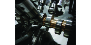
Exhaust Valve Opening
While the timing of the exhaust valve closing is crucial to the efficiency and success of the intake cycle, EVO is crucial for expelling the exhaust gases. The importance of EVO varies in many performance circles from most important to least. The debate varies between engine combinations. Some engine combos can be very lenient while being a crucial selection in others. Which is right? Let’s investigate.
Opening of the exhaust valve allows the pressure from combustion to discharge into the exhaust system. To achieve maximum efficiency from combustion expansion, the desired EVO point would be at or after BDC. It is also advantageous to reduce pressure to the lowest possible value prior to the piston beginning to accelerate back up the bore. To curb pumping losses, valve opening prior to the piston reaching the bottom of its stroke is vital. Both conditions are simple in theory while conflicting in operation. Generally the exhaust cycle begins around 70° before bottom dead center.
Typically in a traditional valve train the exhaust valve is somewhat slow to lift from its seat. The slow lift continues to provide a substantial restriction to flow as the valve begins to lift therefore typical EVO is 50°-60° before BDC in production engines.
A trade-off exists between work lost with gases evacuated before thoroughly expanding and work needed for the piston to overcome exhaust back pressure. A point is reached in any engine combination where opening a valve too soon surrenders more horsepower via the exhaust than gained by reducing pumping losses. The reverse is also true. The force required to expel the remaining exhaust gases from the cylinder may overcome any benefit attained from attempting to maximize the power from the expanding exhaust gasses by delaying EVO. The ideal EVO selection to enhance these benefits differs as gas pressures in the cylinder vary with load and RPM.
Low and part load operation generally benefits as the opening is moved closer to BDC utilizing the extra force from the expanding gases. Low RPM allows sufficient time for the gases to escape as cylinder pressure and exhaust back pressure are similar. Also the remaining exhaust gasses fail to exert substantial force against the slow moving piston.
Higher RPM and load require an earlier EVO as the time for exhaust gasses to be removed is shorter; therefore the time allotted for cylinder pressures to reach exhaust back pressure is reduced. As the exhaust valve is opened sooner higher cylinder pressure reaches the exhaust port. To keep air velocity at its highest more pressure is needed as the time frame is shortened. This is a challenging and critical factor in selection to balance the correct pressure for blow down (removal) without wasting power.
The selection based on RPM is dependent upon the engine combination. A change of a few degrees on a selected combination that can handle a minor change in RPM without sacrificing engine durability, airflow pressure waves, valvetrain etc. will not pose a concern. If not then we fail to maximize horsepower output and performance will suffer.
RPM is typically thought of only in time; however piston speed must also be accounted for. The piston and force of combustion both move in the same direction. As a piston travels down the bore combustion pressure continues to weaken. A slower moving piston therefore will then have more force applied than a piston moving faster. As RPM and piston speed increase, a reduction in force exerted by combustion occurs earlier in the power stroke. (It is understood here that both crankshaft rod length and stroke are extremely critical in piston speed and positon as well).
Cylinder pressure is another factor that must be discussed as it impacts both valve opening timing and the impact combustion on the piston. Higher cylinder pressures apply more force for a longer period of time into the exhaust stroke. Cylinder pressures are also related to volumetric efficiency (VE). An engine operating closer to 100% VE will produce much more pressure for a given valve timing than one running at 80% efficiency additionally affecting exhaust valve opening timing.
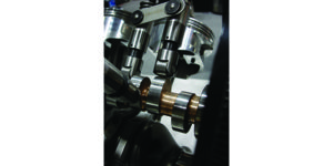
Valve Overlap
As discussed previously valve overlap is the time in crankshaft degrees when both intake and exhaust valves are both open. Remember overlap is ground into the camshaft and therefore not changeable unless a new cam is ground; except for a twin cam engine with separate intake and exhaust cams. Engine builders have been experimenting with effects of duration in a never ending effort to squeeze as much power as possible from an engine build.
Overlap begins as the piston approaches TDC on exhaust stroke continuing up till just after TDC of the intake stroke. This provides the opportunity for intake and exhaust gasses to affect each other and the pressure waves that exist for a given RPM and load. A cam rated with more duration is assured to have more overlap than a cam that shares the same lobe separation angle with less duration. This results not from the actual duration but from the crankshaft degrees the engine rotates with when both the intake and exhaust valves are open.
Valve overlap has the ability to increase the power output by utilizing exhaust gas flow to pull in an air/fuel charge into the cylinder without losing any of this charge into the exhaust system. This results in an increase in the amount of the intake charge that eclipses normal cylinder fill created by the piston draw alone. A properly selected camshaft with the correct amount of overlap can increase power output approximately 20-30 horsepower over an almost identical cam with wider lobe centers.
A camshaft profile for high performance use generally utilizes increased duration to expand the overlap which results in an earlier opening intake valve, and later closing exhaust valve. As a result, intake valve opening is typically the most altered valve timing event followed by the exhaust valve closing that is primarily responsible for setting the ideal amount of overlap. Intake valve opening can range from 50° BTDC on a high performance application to as late as three degrees on an average street engine. The combination of intake valve opening BTDC with the exhaust valve closing ATDC valve establishes overlap. The goal to make valve overlap useful is maximizing power output to the RPM band the engine is designed for. Commonly overlap can range from 60° to more than 100° on a race application, a mild street application operating between 25° to 55°, compared to a stock engine of between 15° to 30°.
The dilemma with overlap is that the results are a benefit for only a given RPM and load range. Higher RPM and loads benefit from increased overlap as the inertia of high speed airflow entering the cylinder is aided by the pressure waves in the exhaust manifold. This extra power does have its drawbacks however. Large overlap often results in poor emissions, rough idle, low vacuum and reduced throttle response under low load and idle operation until engine RPM is high enough to overcome intake reversion. Reversion is affected by both intake valve opening and exhaust backpressure.
The trend on most engines is a rather symmetrical valve overlap that occurs close to TDC. Therefore as overlap is moved away from TDC airflow is subsequently affected by piston motion. Early overlap may result in exhaust gas being pushed into the intake diluting the air/fuel charge. Late overlap may result in exhaust gas being drawn back into the cylinder, again resulting in an EGR effect that dilutes the air/fuel mixture. Low to partial load performance and emissions may benefit from EGR while conversely having a negative impact on high load torque output and therefore undesirable.
Overlap tuning is based on RPM, cylinder head flow, compression, stroke, rod length, rocker arm ratio, exhaust system, engine displacement, combustion chamber size and if needed, streetablitly. Why RPM? While mechanically there is no change in the amount of overlap, the amount of time that is available for cross-flow between the valves is reduced. As RPM’s rise a corresponding increase in valve open time must ensue for both valves to be effective. If not, the “jump start” of the intake charge from the exhaust gas expulsion as well as exhaust gas clearing will be reduced.
A decision based on high RPM operation for valve overlap will exceed the time required for low RPM operation. Dependent upon exhaust flow, a low velocity exhaust system (large tube headers) will result in exhaust reversion, or the opposite condition, where the intake charge passes through the cylinder being expelled into the exhaust. Both conditions result in the same net affect, rough idle, lower torque and increase in emissions.
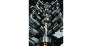
As stated previously there are numerous items besides RPM that impact the amount of overlap required per engine build:
•
Engine Displacement – An increase in displacement without a change in intake port size will require more overlap to aid airflow into the engine.
•
Compression − Higher cylinder pressures are a byproduct of higher compression. This increases the speed of escaping gasses creating a more dynamic scavenging ability, reducing the needed overlap duration.
•
Crankshaft Stroke – Coupled with rod length and rod to stroke ratio affect the amount of time the piston is at TDC; as well as how far the piston travels before and after TDC resulting in the amount of time overlap has to perform its task.
•
Rocker Arm Ratio Combined with Low Lift Port Flow − Affects the intake charge movement at the onset of the intake stroke. Increasing low lift flow via a well-designed port and valve design or increasing the rocker arm ratio will reduce needed overlap.
The ultimate goal of overlap is to combine piston movement with a well-tuned exhaust to enhance the intake draw while at the same time completely pulling the exhaust gas from the combustion chamber reducing intake reversion. The exhaust size has to be large enough to effectively eliminate backpressure at the chosen RPM range while at the same time not being so big that velocity suffers reducing cylinder scavenging. The rules continue to repeat; what is ideal for high RPM doesn’t work well for low RPM.
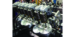
Lobe Separation Angle/Lobe Centerline Angle
Lobe Separation Angle (LSA) is a generic label that indicates the angle, in camshaft degrees, between the maximum lift points, (centerlines), based on placement of the intake lobe and the exhaust lobes. Lobe separation angle is ground into the cam and cannot be changed. However you can advance or retard the cam in relation to the crank when it’s degreed-in which alters the lobe centerline. Regardless of how you install the cam either advanced or retarded, the duration remains unaffected. LSA directly influences valve overlap, which affects the nature of the power curve, idle quality, idle vacuum, etc.
LSA is frequently the least understood and most perplexing factor of camshaft timing. Any change from increasing valve overlap, advancing the intake lobe, retarding the exhaust lobe or any combination of these can change the lobe centerline. Each change made offers contrasting aspects that should be considered both independently and as one. A wealth of complex information exists on Lobe Separation and Lobe Centerline which is much more than can be covered in this article.
Final Thoughts
While no silver bullet theory or calculation exists to determine the “best” camshaft; selection should not be a daunting decision. Experience, the cam manufacturers, or even computer software can help guide you in your quest. Remember to include the complete build and its desired use in your decision making process. Everything from the internal engine design and components, to the manifolds, and final drive ratio will help ensure a satisfied customer. Tradeoffs do exist and must be dealt with. There are no simple valve events, each being unique and possessing the ability to make or break any engine combination. For it’s not always what sounds the best either on paper, or during operation, that produces the desired results we are striving to achieve. Convincing the customer of this may ultimately prove to be the most challenging aspect of the process.

