If we were to sum up the role that the valve spring plays in regard to its function as part of the overall valve train with one word, that word would be control. Considering that it is the predominant part responsible for keeping all of the valve train components in constant contact with the camshaft lobe, it’s easy to see how important getting the correct amount of spring pressure can be. Insufficient or excessive pressure will cause engine performance to suffer, along with the possibility of damage occurring, which can be severe. In conjunction with getting the correct pressure, there are other areas to address that will make sure you’re getting the best spring for the application.
Spring rates are listed in terms of pounds per inch, which simply means that the rating number associated with a particular spring is the force that is necessary to compress the spring one inch. As an example let’s look at a valve spring that has 100 lbs. of pressure at 1.750 installed height. We’ll say that it has a spring rate of 300, which would tell us that it takes 300 lbs. of pressure to compress the spring a full inch. If we have a camshaft providing a total valve lift of .500 then we can calculate the pressure by multiplying the lift by the spring rate and adding that number to the installed pressure to determine the open pressure. It works out as follows; .500 x 300 = 150. Now we take the 150 and add it to our installed pressure of 100, which gives us 250. This tells us that the spring will have 250 lbs. of open pressure at .500 lift. In order to have a comparative context, we’ll use the same dimensions but employ a spring that has a 350 lb./in. rating. Our installed pressure can be the same but calculating the different rate spring ( .500 x 350 = 175 ) and adding to our closed pressure of 100 lbs. shows that we now have 275 lbs. of open pressure on the same installation due to the increased spring rate.
The same formula can be used to determine the closed pressure because most manufacturers seldom list the free length of the spring to calculate with. Using the previous specs listed, if we move from a 1.750 installed height to a 1.700 with the 350 lb./in. spring rate it would work out as .050 x 350 = 17.5, which when added to the 100 lb. figure at 1.750 would now give a closed pressure of 117.5 or roughly 118 lbs. If we were increasing from the 1.750 height to a 1.800, then you would subtract that amount which would produce 82 lbs.
The parameters for spring selection will be closed pressure, open pressure at maximum valve lift, coil bind height, retainer-to-guide clearance and fitment of the spring retainer and spring seat base. The main factors of the valve train that come into play on this are the weight of the components, how high the engine will RPM and the profile of the camshaft lobe. When determining the spring pressure, most manufacturers suggest the following guidelines;
Hydraulic flat tappet cams for small block applications should be in the 105-125 lb. range on the seat. Big blocks can use 115-130 lbs. due to having longer and heavier valves. Open pressures shouldn’t exceed 330 lbs. in order to provide a good service life for the cam and lifters. You also need to have a minimum open pressure of 260-270 lbs. for performance applications, but can utilize less if you have lighter weight valves and retainers. Engines that operate with 4,000 RPM or lower maximum (such as some airboats for example) can get away with a 220-230 lb. minimum pressure, but anything less than that in a hydraulic flat tappet build won’t offer decent, long-term valve control. Another area of the cylinder head to consider with any open spring pressure that exceeds 275-280 lbs. is the possibility of OEM-style, pressed-in rocker studs coming loose. In these applications it’s always good insurance to install screw-in rocker arm studs.
Hydraulic roller cams need higher seat pressures to control the heavier weight of a roller tappet and the more aggressive opening and closing rates of most roller cam lobe profiles. Small block applications should be in the 120-145 lb. range for seat pressures with big blocks being in the 130-165 lb. range. They also require higher open pressures for the same reason, to control the vertical opening inertia of the heavier roller lifters. High performance small block applications like 300-360 lbs. open spring pressure with higher end and competition builds being able to use 400-425 lbs. open pressure while still achieving reasonable valve train life. When using a spring that produces an open pressure in excess of 360 lbs., the springs, lifters and push rods must be of top quality materials in order to endure the higher spring load. In the same manner that a lower opening pressure can be used on flat tappet engines operating at a lower RPM limit, you can use a spring that will provide a 260-270 lb. minimum for hydraulic roller applications operating at 4,000 RPM and lower.
Big block applications for general performance and lower RPM operating ranges need at least 280 lbs. open pressure and should have 325-375 lbs. for higher performance levels. Seriously high output and competition engines can push up to 450 lbs. open pressure. Again, like a small block, elevated spring pressures in excess of 360 lbs. dictate high quality valve train components to keep the engine performing consistently. In both small and big block hydraulic roller engines, stock OEM style roller lifter bodies won’t tolerate open pressures above 360 lbs.
Flat tappet mechanical cams can be somewhat of a different animal in regards to setting up your spring pressures. Generally 130-145 lbs. on the seat with an open of around 350-360 lbs. should be adequate, but certain applications, particularly higher RPM builds, can be done with increased pressures. We have built a fair amount of small block circle track engines that were pushing the needle close to 8,000 RPM using mechanical flat tappets and the installed was 160 lbs. with an open pressure of 390-410 lbs. These builds utilized lightweight parts and coated lifters with EDM oiling. The main thing I would like to stress here is the break-in procedure. Pull the inner spring or break it in with a different set of lower-pressure springs. It is additional work, but it is the only way to do it correctly.
Mechanical roller cams and lifters were originally used in full competition applications with some usage in specialized street builds that mostly saw limited driving. Today, there is a much larger number being employed and many manufacturers have dedicated grinds for engines that are used in places other than the race track, including daily drivers. For the most part, these cams are designed with very aggressive opening and closing rates. Higher seat pressures are required to keep the valves from bouncing when they come back to the seat. Milder solid roller cams can use 165 lbs. on the seat, but that is the minimum you should try to use. The majority of performance cams will need 180-200 lbs. closed. Competition applications will be in the 220-250 lb. range with upper level competitive engines utilizing as much as 350 to 500 lbs. on the seat. Open pressures have to be high enough to control the valve train as the lifter follows the cam lobe through maximum valve lift. Street and general performance applications can use a range of 350-450 lbs. over the nose that will help add a longer service life to the cam and lifters. Most drag racing and circle track builds will be in the 450-600 lb. range. Professional drag racing and other highly specialized engines are built with over 1,000 lbs. of open spring pressure.
Avoid Excessive Movement
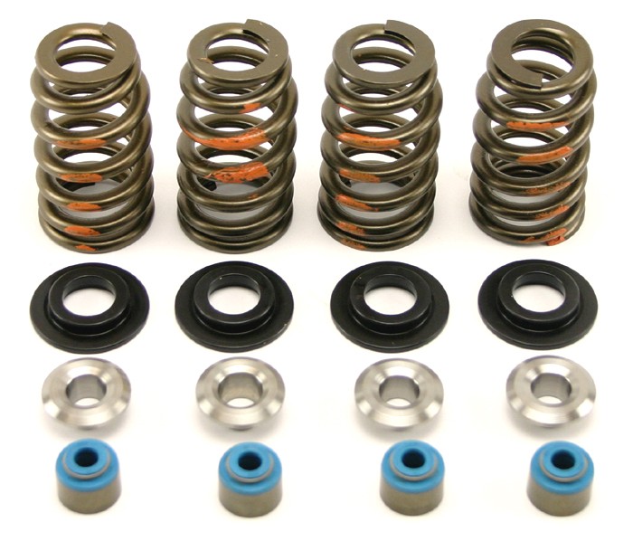
One very important area when working with valve spring installation is to make sure that your springs are positively located. The retainer should fit snugly inside the spring and also the inner springs as well for dual and triple-spring applications to prevent any movement other than compression and rebound. Too much clearance will allow the spring to “walk” around causing abnormal wear to both the spring and retainer. The fit of the retainer also shouldn’t be too tight as this can overstress the top coil causing it to fail. As with the retainers, the fit inside the spring pocket of the cylinder head should keep the spring from moving around. Excessive clearance on the head will allow the spring to eat away at the mounting surface and damage the spring itself. If the fit is too tight it will overstress the bottom coil causing it to wear against the head and prematurely fail. When using spring cups, they should fit the ID of the valve spring and also have the correct fit for the OD of the valve guide.
Spring Designs
Modern advancements in materials, finishing processes and even wire shape have given us more options in spring design choices than ever before.
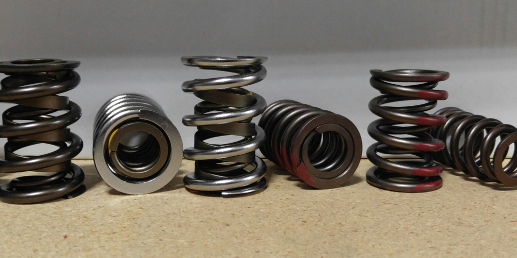
The cylindrical style is available as a single type, single with a flat wound damper spring, dual and triple spring. This type of spring has been used in just about every application imaginable, from OEM’s to every form of racing. The dual and triple springs work well for performance and competition builds because of the higher loads derived from utilizing multiple springs. Aftermarket manufacturers have made great strides in materials and finishes that have brought these springs to a much higher level than was available in the past.
Beehive style springs have a base like the cylindrical spring, but taper to a smaller diameter at the top. Since the top of the spring is smaller and therefore can use a smaller diameter retainer, the weight is reduced. This increases RPM potential with less spring load needed. A large majority of beehive-type springs utilize an ovate wire as opposed to round wire. Ovate wire designs provide a distribution of additional material in the high-stress areas of the spring, which spreads out the stress load.
Conical-style springs are similar to the beehive design in regard to the upper portion of the spring being a smaller diameter than the base, which achieves the benefit of weight reduction, but is cone shaped from bottom to top instead of tapering like the beehive. The coils of a conical spring differ in diameter and spacing, which results in a progressive frequency that provides a natural damping effect. I would really like to discuss this area further but it’ll have to wait till another article.
Remember to check for coil bind when installing springs. You should keep a minimum of .060 between coils. Check the retainer to valve guide clearance (allow room for the valve seal if it isn’t installed when taking your measurement). Also, make sure that there is sufficient clearance between the spring retainer and rocker arm. Till next time, have fun making horsepower!


