Life is a series of compromises. Human relations almost always
involves compromises of some sort. You want Chinese for dinner,
she wants Italian; something has to give. Even if you go your
separate ways, it’s a compromise and a decision to not dine together.
Believe it or not, it’s the same with machinery. Any exercise
in design is a compromise in time, cost, service, longevity and
a host of other factors. When it comes to building a high performance
marine engine, developing a combination is no exception – a compromise
must be made at each step of the process from initial performance
goals to final cost.
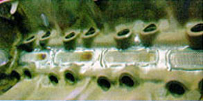 Debris screens
in lifter galley prevent broken parts from going to the pan.
The biggest mistake I see made in what I call the semi-racing
market is the mismatching of components. It is due to a lack of
understanding of the compromises that must be made to tailor a
performance engine to the needs of the customer (remember, that’s
not necessarily the same as what the customer wants). Magazine
articles touting the benefits of the latest and greatest piece
of speed equipment have been the ruination of many engines that
could have performed better if a more realistic approach had been
taken when selecting the components. I call this the "gee
whiz" factor.
Be sure to check both inner and outer springs for coil bind.
More often than not, the customer reads about the latest hot product
in a magazine article and toy fever sets in. "That’s just
the ticket to pep up the 302 V8 in my full size Bronco 4×4,"
he thinks. Never mind that the engine in the article (also a 302)
was installed in a 1200 lb. kit car. Examples like this can be
made for everything from carbs to high-volume oil pumps. And,
of course, if you sold it to him and it doesn’t work, you don’t
have to look very far to find the person he’s going to blame.
In the marine market, there are a number of compromises that are
unique to the industry. These are primarily dictated by the type
of boat and drive system. The need for the engine to idle slow
enough to maneuver in docking areas and observe mandatory no-wake
zones is one consideration; the use of an outdrive pretty much
limits the engine to 6000 rpm unless the boater in question is
willing and capable of frequent maintenance on the drive. V-drives
and jet boats present their own unique problems, with the type
of boat making a big difference in the engine required for best
performance.
Let’s take a look at the recent build-up of a 523 cid big block
Chevy for a marine application using a Mercruiser Bravo drive,
and detail most of the compromises I made to tailor the engine
to the application and owner.
Horsepower is a function of torque and rpm. More torque at any
rpm equals more horsepower. The same torque, developed at a higher
rpm equals more horsepower. Did you get that? Read it again. 300
ft. lbs. of torque at 3000 rpm is 172 horsepower. But 300 ft.
lbs. at 6000 rpm is 344 horsepower, double the rpm and double
the horsepower.
In other words, make it breath at higher rpm, and it makes more
horsepower. Unfortunately, in marine applications, high rpm is
not always practical, so the puzzle is more torque/horsepower
without significant increases in rpm. There are a number of ways
to make more torque (more compression for one), but my preference
is more cubic inches. Bigger is definitely better in my opinion,
because even though the initial cost is higher, there is no additional
maintenance just because it’s big.
Herein lies the first compromise. How big can we afford to go?
In this case, the customer wanted to use the crank and rods from
his old engine. Bummer. I would have preferred to at least use
longer rods and a tall deck block to get a more favorable rod/stroke
ratio. But since the rods were good 7/16 bolt units and the crank
was standard and in good shape, they were retained for the new
engine.
So the only remaining way to get cubes is a big bore. I have successfully
used a 4.60" bore in a Chevy bowtie block; a Dart Merlin
block was out of the question because of the additional $1,000
price tag. Actually, in this application I prefer the Chevy piece
because of the lighter weight. A 4.56" bore was settled on
to leave some room for future rebuilding (compromise).
Since the reason for this project is to replace the 454 that the
customer broke at the start of the boating season, there was no
time to order a set of pistons with optimum deck height and compression
ratio. Thus a set of off-the-shelf flat top forgings from JE were
ordered. I like the JE pistons because they can be run at .004"
to .005" on skirt clearance instead of the .008" to
.010" required with other brands.
Using 120 grit finish in the intake ports helps to keep fuel suspended at lower rpms.
The tighter clearance results in less piston noise and longer
ring life. The main compromise was in the interest of time. While
I don’t like the standard 1.645" compression distance of
most off-the-shelf pistons because it requires decking the block
.020" to get my preferred zero deck height (I do prefer tight
ring grooves and a relatively high ring placement) the off-the-shelf
items are an acceptable compromise to waiting six to eight weeks
for the pistons.
The block was given minimal prep, the main bores were checked
for size and straightness, the cylinders bored and honed, hot
tanked, and debris screens epoxied into the lifter area. It was
not line honed, decked, torque plated, block trued, bore trued,
or lifter trued, and only a small amount of hand grinding was
done to ensure that no casting flashing would break off and enter
the oil supply. The compromise here is the lack of a full boogie
prep of the block in the interest of cost and time. But it still
provides a cost effective component that will give good service.
ARP 7/16 rod bolts were installed in the otherwise stock rods,
and they were resized to the low side for maximum crush on the
bearings and .0015" press on the pins. I balanced the rods
and pistons, and the pistons were hung in place and the rods checked
for straightness. Nothing fancy – no polishing, no shot peaning,
just the basics. As previously stated, I would have preferred
aftermarket rods about 6.600" to 6.800" in length, not
for strength, but for the added length, but the $1,200 cost was
prohibitive.
I generally like to Magnaflux® the crank and rods, but considering
that this crank had never seen 5000 rpm before, magging was vetoed
in favor of what? That’s right, time and money. Another compromise.
The crankshaft checked high side on the mains and .0002"
under the high side on the throws which resulted in .0024"
to .0025" clearance on the mains and .0021" to .0022"
on the rods; rod side clearance was .018" to .020".
Considering the relatively low rpm of this type engine (5500 to
5800), and the fact that it is equipped with an oil cooler, I
prefer stock numbers on both bearing oil clearance and rod side
clearance. I calculated the bobweight and sublet the crank, flywheel,
and harmonic balancer to a local balance shop.
Assembly of the short block is pretty routine. I removed the cam
bearings that were in the block as supplied by GM before it was
hot tanked, and I reinstalled them in their original location
because replacement cam bearings often seem to have more clearance.
At one time I was chasing a low idle oil pressure problem in Chevy
400 small blocks and discovered that the bores in the cam tunnel
for the bearings were not very consistent, resulting in as much
as .005" to .008" bearing clearance with new bearings.
I made a self piloting cam bearing reamer used in my line hone,
installed .010" under cam bearings and reamed them to size,
giving me .001" clearance. This was before I finally traced
the problem to the lack of rod thrust face on the 400 crank.
Welding the sides of the throws and regrinding the crank so that
it has a full 360ºof face next to the rod solved the oil
pressure problem. However, since then I have always been sensitive
to cam bearing clearances. Engine builders I have talked to believe
that as long as the oil hole in the bearings are down, cam bearing
clearance is not a problem. Others simply use a high volume oil
pump to compensate for any problems. But to me this approach increases
the oil demand of the engine, increases wear on the distributor
and cam gears, and is like aiming for the other fairway because
you have a slice, instead of correcting the slice.
I prefer Federal-Mogul Corp. bearings as they don’t seem to flake
on the surface or delaminate, and in this engine I used the FM
competition series bearings with the 3/4 groove in the mains,
and chamfered rod bearings. ARP specifies the rod bolts be torqued
to a stretch of .0078" to .0082" with moly lube on the
threads, and 75 ft. lbs. as an alternative. These bolts required
an average of 86 ft. lbs. to stretch them to the desired .008".
By the way, I have my torque wrench calibrated annually to ensure
it’s accuracy. If you don’t, you should consider doing it.
Modified short turn radius in the port.
The bottom of the engine is finished up with a stock oil pump.
I lapped the pump body and cover on a surface plate with 360 grit
paper to remove machine marks for a better seal, and established
the end clearance of the gears at .0025" to .003". A
factory windage tray and the stock Mercruiser 365 oil pan was
used, and is the same as that used on a 427 in a Chevy C-60 truck;
it holds eight quarts.
I heliarc tack-welded the pickup screen to the pump body with
silicon bronze rod in two places as a precaution to keep the screen
from falling out. After installing the pump, I trial installed
the pan and with 10W oil, ran the oil pump with an old distributor
and a drill to check for 60 to 65 lbs. of oil pressure. It usually
takes one to two washers under the spring to get that. With 10W
40 oil it should make about that much pressure at 5000 to 6000
rpm.
Camshaft selection is a black art. That is unless you have unlimited
time on a dyno and a truck load of cams to try. Maximum horsepower
generally dictates the maximum rpm that the engine can structurally
withstand, and that means lots of duration, lots of lift, wide
lobe separations and short life.
In general, for any given duration and lift, a solid lifter cam
will make more horsepower than a hydraulic cam, and a roller will
make more power than a solid flat tappet. As you move from a hydraulic
to a solid to a roller, the potential velocity of the valve is
higher, which means more lift for any given duration.
In this case, the money was spent to get the most horsepower,
and that means a roller cam. Since power above 6000 rpm was not
a consideration, the compromise becomes one of getting maximum
lift and duration without sacrificing the idle and low speed qualities
necessary to operate the boat in a marina environment.
The cam selected was a Comp Cams 284-6/288-6 R114. It has 284/288
advertised duration (at .020"), and 254/258 at .050".
Lobe separation is 114º and it has .690 gross lift. Tighter
separation angles would enhance midrange torque, but at the expense
of good idle quality.
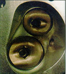
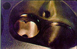
Unshrouded chamber laid back from exhaust valve in quench area.
The cam is installed with a 106º intake center line, again,
to enhance idle quality and midrange performance. I use rev kits
when possible to reduce lash shock on the lifter and to keep the
lifters in place in the event of a failure of a pushrod, rocker
arm or valve spring. Comp Cams stainless roller rockers, and a
stud girdle finished out the valve train. The stud girdle is to
keep from breaking the stud bosses out of the heads.
Shaft mounted rockers would have been a good alternative to the
stud girdle, but again the compromise was made for the lower cost.
In retrospect, this created another problem because the only valve
covers that would work with the girdle and still clear the Gill
marine exhaust manifolds were the B & M two-piece covers which
are heavy and expensive. So some of the economy of the girdle
vs. shaft rockers decision was offset by the expensive valve covers.
A Cloyes True Roller timing set was installed behind an Edelbrock
aluminum timing cover. I was disappointed with the Edelbrock timing
cover because the spot facing for the bolts made it difficult
to install the regular GM timing tab, and the area ahead of the
cam flexed rather easily. I also had to shorten the cam button
to make the whole thing fit. This is unusual for an Edelbrock
product. I have always found their parts to be superior in both
fit and performance.
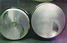
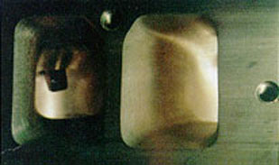
Shown is an .030″ 454 piston compared to the 4.560″ for the 523. Bigger is definitely better.
The block is topped off with a pair of aluminum Chevrolet "C"
port heads, c/n 14011077. These are a later version of the L88/Zl-1
head and are similar to the square port, open chamber, cast iron
head with a better exhaust port, and a smaller 295cc intake port.
They were selected because one of the original iron heads was
wounded from a broken valve, I had these in stock, and the porting
was almost finished. There are more recent designs available that
may have made a little better power. They are also considerably
more money and the time to do the porting wasn’t available. Another
compromise.
The roofs of the intake ports were raised .100" and opened
up to 320 cc. The bowls were cleaned up, the guides narrowed and
the ports finished with a relatively course 120 grit tootsie roll.
The vanes in the exhaust ports were narrowed, the bowls finished,
guides narrowed and tapered, and the chambers opened up to unshroud
the valves and bring them out to match the bore; 2.19 and 1.88
Sealed Power stainless valves were fitted.
Intake seat angles are conventional 30/45/60, and the exhausts
have a 37/45/53 angle combination. The valves are back cut to
the seat lap line at 30º on both intake and exhaust. I prefer
a rather wide .050" intake and .080" exhaust seat width
to help cool the valves. The top cut is carefully blended to the
chamber to eliminate any step, and the bottom cut blended to the
bowl.
After a .025" angle mill plus an additional .020", the
chambers were 118 cc. Valve springs are Competition Cams #919
chrome silicon, set at 200 lbs. on the seat, and 565 lbs. open.
Comp Cams does not recommend the H-11 type spring in endurance
applications because they are more brittle than the chrome silicon,
and even though they hold their pressure better, tend to break
more readily. A better, but of course more expensive, alternative
to these springs would be the Pacaloy NASCAR spring that they
make. Another compromise.
The reason for opening up the intake ports is the stock rod length.
If I had been able to use a longer rod, a smaller port would have
been beneficial to keep the mid-range torque up. The short rod
generates higher piston speed as the piston moves away from top
center during the intake stroke and the bigger port is beneficial
in providing a reservoir of mixture for the cylinder to draw from
during this period.
This is an area to watch in engines you build. The velocity of
the intake mixture is relative to the size of the port; the bigger
the port the better the engine breathes at high rpm, but the lazier
it will be at lower rpm and visa versa. For a 500 cid prostock
drag motor, ports in the 380cc and bigger range are common because
of the very high rpm and narrow power band used in this type of
racing. Obviously, there are many considerations involved here,
and a complete discussion of relationships involved is beyond
the scope of this article.
I don’t feel that a 9.0:1 compression motor needs head studs,
but the customer wanted them, and since they don’t have any negative
impact on performance and are definitely better parts than stock
head bolts, why not compromise. Well…why not turned out to be
that the studs in the ARP kit were just enough too long that the
short outer ones would not clear the Gil exhaust manifolds. So
now we have four head bolts instead of studs in each head. Compromise
on the compromise.
When I was in my formative years, multiple carb setups were the
gee-whiz, gotta-have-it item. Three twos, dual quads, six and
even an occasional eight two-barrel log manifold with Stromberg
97s would grace the engine compartment of every serious performance
toy. It was common to see an engine that was so over carbureted
that full throttle couldn’t be used until almost maximum rpm,
otherwise the engine would bog.
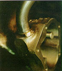
Tack weld pickup to the pump body.
The air velocity through the carbs would fall to the point that
the boosters wouldn’t pull the fuel from the bowls, and the engine
would go lean. I once saw an Olds-powered roadster with a two-barrel
manifold and three two-carb adapters stacked up so four two-barrels
fed into the place where the single two-barrel formerly fit. It
looked like antlers on a reindeer. Didn’t run so good either.
Back then there was a shortage of people that understood carbs
in quantities of more than one. Well, those people are in even
shorter supply today, and for good reason. With the manifolds
and carburetors available today, it’s become fairly routine to
build single carburetor motors developing more than 800 hp.
The point is that it’s not realistic to saddle your customer with
multiple carbs (even when he wants them so bad he’s about to wet
his pants) that in all likelihood won’t ever run up to their potential.
There can be no argument that the potential performance of a tunnel
ram and two fours is superior to that of a single four-barrel,
dual-plane or X-type manifold, principally because of the more
direct path from the carb to the valve. But if you factor in the
person that has to tune and maintain it, the sensitivity to climatic
changes and, if it’s to be used in northern latitudes, the effects
of cold weather on an unheated manifold, you will probably find
in favor of the simpler single-carb set up.
And, as you know, there is no shortage of super tuners out there
that can screw up a single four installation. By the way, the
Holley marine catalogue has a little chart to help determine the
proper carb size for your application.
The compromise here is for a Dart single four manifold for a 4160
carb, a Holley 2" spacer/1050 adapter, and a 1050 dominator,
as opposed to an electronic fuel injection which I would consider
to be the desirable option. The reason for the spacer is twofold:
first and most important is to generate a smoother radius from
the plenum to the roof of the runners. Second, it provides some
additional volume under the carb which will help the top-end power
some.
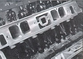
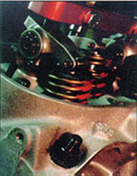
The completed valvetrain. Rev kit keeps the lifters in their bores
if something breaks.
I expect this engine to have slightly more than 100% volumetric
efficiency, which makes an 850 cfm the best carb choice. But there
are currently no 850 marine carbs available. If this were a 454,
I would have used a 750 instead. Since this engine has more than
enough low-end power to get the boat on plane, and the customer
wanted the dominator, that’s what we installed, topped with a
K & N flame arrester.
In writing this article, I have kept in mind that you already
know the mechanics of the machine work, and how to put the rings
on the pistons, so my intent is only to point out my own thoughts
on developing an engine combination for a specific application
with the realization that there is more than one way to skin a
cat. My approach can be summed up by saying that I prefer long
rod to stroke ratios (1.8:1 or better) smaller ports, lots of
valve lift, conservative clearances, tight piston to head clearances
(.035" to .040"), and as much compression as the intended
fuel will stand.
I have learned a lot of the lessons that I use to develop combinations
by reading about other people’s approach to a certain problem
and asking myself if it is appropriate to what I do. I invite
you to question the things I have suggested here, and, keeping
in mind that a book could be written about any of the individual
points I have made (and probably already has been), investigate
other sources of information to develop your own approach to these
compromises.
Just keep in mind that a successful engine is the result of a
well thought out combination of pieces that satisfy the compromises
you identify when you start the project. To me the fun in building
engines is developing a combination of your own that kicks butt
on the rest of the crowd while spending a lot less money to do
it. AR
Specific manufacturer’s parts mentioned in this article does not
represent an endorsement or lack of endorsement of those products
by Automotive Rebuilder magazine. Parts used represent the author’s
specific part combination preferences based on experiences and
stated rebuilding goals.
Ken Weber is the former owner of Marine Engine Service, Inc.,
a production engine rebuilding business that specialized in inboard
marine engines. Currently employed as an automotive extended claims
adjuster for General Electric Capital Corp., Denver, CO, Weber
builds six to eight marine performance engines each year.