Take a look in the mirror. Smiling back at you, you’ll notice that row of pearly whites. They probably look pretty good. Maybe a bit stained from coffee or smoking, but overall, they seem to be pretty solid, right?
If you’re like many people, the fear sets in as soon as you sit down in the dentist chair. Has your daily ritual of brushing and flossing been enough or was the tempting bowl of hard candy on your shop counter too much to resist? What kind of damage have you subjected your teeth to this time – and what kind of repair work will be necessary?
Calmly, the dentist examines your open mouth, offering no indication of her findings except for the occasional “hmmm…” It’s not until she pulls out the lead apron that you know she’s going to be looking beyond the surface – for subsurface defects that may lead to expensive repairs or assurances that the choppers are in good shape for continued chewing.
Like your dentist, engine builders are faced with the need to look for damage to parts that need to be repaired or replaced. But unlike the dentist, engine builders have a variety of methods available to them to help detect cracks, flaws or other anomalies that may lead to damage down the road.
Though some cracks may not be a serious concern (depending on their location), others can cause problems. And even if a crack isn’t very big or isn’t leaking now, there’s no guarantee it will stay that way.
Cracks tend to form, spread and get worse as the heat, thermal stress, heavy loads, repeated bending and flexing, metal fatigue, pounding and vibration take their toll on the part. So if metal is pulling away from metal, it means an area is experiencing more stress than it can handle. That’s why cracks form in the first place.
Because engine parts are no longer made just of cast iron or steel, you need alternative methods of looking for cracks in those parts. The competitive nature of this business means you can’t afford to spend a lot of time machining or reconditioning cores or used parts that may be flawed.
If critical parts are not inspected for cracks, there’s no way to know if they will stand up to normal use and abuse. In the case of cylinder heads and blocks, you won’t know if the castings can hold pressure until the engine has been assembled – which means you may have wasted a lot of time and effort if a casting turns out to be full of holes.
And it’s not only cracks that you should be on the lookout for: other flaws such as porosity leaks in castings need to be identified so a decision can be made as to whether repair or replacement is the best option. With hard-to-find and high value cores and parts, the decision may hinge on the extent of the damage. If the part can be repaired economically and with a high degree of success, then it’s probably worth fixing. But if it can’t, you’ll have to factor in the cost to replace it.
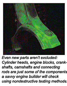
Even new parts aren’t excluded: Cylinder heads, engine blocks, crankshafts, camshafts and connecting rods are just some of the components a savvy engine builder will check using nondestructive testing methods. There are a variety of techniques that can be used by themselves or in combination with other methods to find cracks in castings and other components. These include magnetic particle inspection, various types of penetrating dyes, pressure testing, vacuum testing and ultrasonic (acoustic) testing.
Cracking Up
Cracks are quite common in late model cylinder heads and are often found between valve seats, in exhaust ports, between the spark plug hole and valve seats, around valve guides, between combustion chambers, and even on top of the head.
The blame is often placed on thinner castings and higher engine loads, but in many instances the underlying cause is engine overheating due to a cooling system failure (coolant leak, inoperative cooling fan, stuck thermostat, etc.), or a detonation problem (carbon buildup, inoperative EGR valve, too much ignition advance, etc.) or some other user (or builder) error such as incorrect installation (wrong torque on head bolts, dirty bolt threads, etc.).
One of the causes of cracking in cast iron heads is stress created when the valve seats are induction hardened. The concentrated heating process that hardens the valve seats also creates residual stresses in the head that may cause it to crack later – even if the engine has never overheated. The cracks typically form where stresses are highest, which is often between the valve seats.
Cracks typically form when a cylinder head undergoes too much thermal stress. Loss of coolant – severe overheating as well as sudden changes in operating temperature from hot to cold – can all create the conditions that can cause cracks to form.
Simply put, when metal is heated it expands. Aluminum expands at nearly twice the rate of cast iron, which creates a mismatch in expansion rates on bimetal engines with aluminum heads and cast iron blocks. While the heads are designed to handle a certain amount of normal expansion, elevated operating temperatures can push a head beyond those design limits, causing the metal to deform. This, in turn, may cause cracks to form as the metal cools and contracts.
When overhead cam heads get hot, they often swell and bow up in the middle. This may cause the OHC camshaft to seize or break as well as cracks to form in the underside of the head. Pushrod heads are not as thick as OHC heads so are less vulnerable to this kind of stress and warpage. But even pushrod heads have their limit, and when pushed too far will also warp and crack.
If a crack forms between the cooling jacket and combustion chamber, port or any other external surface on the head, it may leak coolant. If the leak is in a combustion chamber, it may go undetected until the engine overheats from a loss of coolant. Coolant in the combustion chamber can accelerate ring and cylinder wear and is murder on the bearings. If the leak is large enough, it may even hydrolock the cylinder.
When cracks form between the cooling jacket and combustion chamber, coolant will enter the combustion chamber. Steam is quite effective at decarbonizing the combustion chamber, but it also washes away the lubricant from the rings and cylinder wall, which accelerates wear. One “quick check” for coolant leaks in used cylinder heads and blocks is to simply note the appearance of the combustion chambers and pistons when the engine is torn down. If a combustion chamber or piston lacks the normal accumulation of carbon deposits, it probably has a coolant leak in the head or cylinder.
Combustion gases entering the cooling system through the crack can also accelerate coolant breakdown and corrosion. Pressure testing the block and heads to see if they hold pressure is a good technique for finding these kind of “hidden” cracks as well as porosity leaks in aluminum castings.
Coolant contains silicone, and if it leaks into the exhaust system through a crack in an exhaust port it can expose the oxygen sensor and catalytic converter to silicate contamination if the cooling system is filled with conventional green formula coolant or a hybrid-OAT type of coolant. Silicates have the same coating effect on these components as lead, and will eventually ruin the O2 sensor and converter.
External coolant leaks due to cracks are not as common because the outside of the head runs considerably cooler than the combustion chamber and exhaust port surfaces. Even so, cracks sometimes form in these areas that leak coolant.
“Dry” cracks that do not leak coolant may or may not cause problems depending on where they form. Cracks between or around valve seats in an aluminum head may allow the seats to work loose and fall out. Cracks around valve guides may lead to loosening of the valve guides, which can damage the valves.
Some heads, such as the Ford 2.9L V6 and Escort 1.6L heads, are notorious for cracking. Ford’s “HSC” (High Swirl Combustion) cast iron heads like those on the 2.3L and 2.5L OHC engines, General Motors 2.5L “Iron Duke” head, the GM 250 six-cylinder head with an integral exhaust manifold, and 1987 and later Chevy small block V8 “Vortex” heads have also historically been prone to cracking. The same goes for some of the older SL1 and SL2 Saturn aluminum heads. Dodge hasn’t been immune to crack damage either: almost all of the cast iron heads on the 318 Magnum engines have been reported to have cracks between the valve seats when the engines are rebuilt.
Cracks in crankshafts, camshafts and connecting rods can lead to breakage of these parts, too. In such cases, you don’t have to look for the crack if the part has already failed. What you do have to look for are any underlying causes that may have contributed to the formation of the crack or caused the component to fail.
For example, most broken camshafts in an OHC cylinder head are not caused by flaws in the camshaft. They’re often caused by engine overheating. The head gets too hot, warps, seizes the cam and causes it to snap.
The same goes for broken crankshafts, except the list of possible causes is longer. Many factors can lead to a broken crank, including an incorrect radius when the crank journals were machined, a severe engine detonation problem, bent connecting rods, a loose main bearing cap, main bore misalignment, a bent crank, a severe engine imbalance or an imbalance in the vibration damper, flywheel, clutch or torque converter.
Though many cracks may be clearly seen once parts have been disassembled and cleaned, other cracks are nearly invisible or may only be seen under special conditions (such as porosity leaks in heads and blocks). Other cracks may be entirely hidden , such as those inside a casting.
Never assume a part or a casting is okay just because you can’t see any visible cracks. Always assume there may be cracks.
Magnetic Particle Inspection
This technique can be used to find cracks in cast iron or steel alloys that are “ferromagnetic” and can be temporarily magnetized. Magnetic particle inspection won’t work on nonferrous metals such as aluminum, magnesium, titanium, nonmagnetic alloys of stainless steel or plastic.
Magnetic particle inspection is most often used to inspect cast iron cylinder heads for surface cracks in and around the combustion chambers, and for inspecting crankshafts, camshafts and connecting rods. But the technique can also be used to check gears, shafts, axles and steering and suspension components for cracks, too.
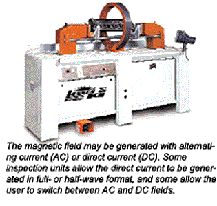
The magnetic field is created by a permanent magnet, an electromagnet or by passing a part through a large magnetic coil. Tiny iron oxide particles are then sprayed or brushed on the part to reveal any cracks. If there are any cracks in the surface of the part, they will disrupt the magnetic field and act like a pole to attract the iron particles.
The iron particles used to detect cracks are finely divided in sizes varying between .125″ and 60 microns, are easily magnetized but don’t stay that way for long (so they don’t stick together or to the metal being tested and can be reused). The particles may be in a dry powder or a wet solution. Particles are dyed yellow, white, red, gray, black or with a fluorescent color to improve their visibility against the metal background. With the fluorescent particles, an ultraviolet black light is required to make the particles stand out.
Dry particles may be applied with a squeeze bulb or spray gun. Wet particles may be mixed with an oil- or water-based liquid or paste. The wet particle detection method is more sensitive than the dry method for finding very small cracks, but dry particles are better for finding cracks that may be just under the surface (subsurface flaws).
There are two basic methods of applying the solution containing the
particles. The “continuous method” is good for low carbon materials, and involves turning on the magnetic field immediately after the part has been “washed.” The “residual” method works well for higher carbon materials, and involves magnetizing the part first and then flushing the part.
With nonfluorescent particles, you want plenty of light on the part to improve visibility. With fluorescent particles, you need to aim the black light so it illuminates the test area completely. Fluorescent particles are usually easier to see than the nonfluorescent ones. Either way, be careful to keep the light away from the magnets or magnetic coil because the powerful magnetic field may bend and break the filament inside the bulb.
When checking for cracks, the stronger the magnetic field the more easily it will reveal cracks. For this reason, more powerful electromagnets or magnetic coils may be better than less expensive permanent magnets. The magnetic field may be generated with alternating current (AC) or direct current (DC). Some units also allow the direct current to be generated in full- or half-wave format, and some allow the user to switch between AC and DC fields.
Magnetic fields generated with alternating current flow across the surface of the part, which can help locate subsurface variations along the “skin” of the part. Fatigue and seizure cracks often originate on the surface and expand along it. AC lends itself very well to surface and shallow crack detection, about .100″ to .250″ below the surface of the metal.
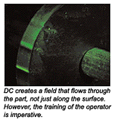
DC creates a field that flows through the part, not just along the surface. This allows an experienced user to locate inclusions in castings, such as poor welds or weld inclusions or other deeper anomalies (typically, DC can locate flaws up to .250″ to 300″ deep). It is also useful for finding flaws in tubular applications, rods and other similar components. However, the training of the operator is imperative. As one magnetic particle inspection trainer explained it: “While AC current shows cracks, DC shows shadows. You are literally chasing ghosts,” he said.
The direction of the magnetic field is also important. A “head shot” detects flaws along the horizontal plane of the part, and a “coil shot” detects flaws on the vertical plane. The lines of force must cross the crack at an angle to reveal its presence (45 degrees usually works best). If the magnetic field is parallel to a crack, there may not be enough distortion in the field to attract any particles. So if you don’t find a crack when holding the magnets or part one way, rotate or reposition the part or magnets 45 to 90 degrees if possible and repeat the test.
Sometimes, casting lines or a rough surface finish on the component that’s being inspected can hide cracks. That’s one of the reasons parts should have be as clean as possible with no dirt, oil, grease or carbon on the surface. Parts can be chemically cleaned, spray washed or baked in an oven, but don’t shot blast them prior to inspection because blasting may peen shut small cracks that could reopen later.
Often, castings will show various surface flaws that are not really cracks but only minor surface scratches, sharp section changes, magnetism caused by cold working a part, weld metal/base metal zone edges and the edges of decarburized zones. On these types of defects, you have to make a judgment call as to whether or not what you’re looking at is actually a crack – and if it is, if it’s worth worrying about or not. A small hairline crack in a non-critical area of a cylinder head may not be a problem, but a hairline crack in a crankshaft journal or between a spark plug hole and valve seat in a combustion chamber could mean trouble.
Parts should be checked for cracks after they have been cleaned and before they are machined or used for assembly. A second check for cracks should also be made after certain kinds of reconditioning operations have been performed to make sure any original cracks have been eliminated and/or that no new cracks have appeared. This might include rechecking a cast iron head after pinning or welding an existing crack or installing a machined-in valve seat, checking a block after installing a cylinder sleeve, checking a crankshaft after it has been straightened, etc. It’s just added insurance to make sure there are no cracks that might cause problems down the road.
One of the most important parts of magnetic particle inspection comes after the testing has been completed: the demagnetization of the part. According to experts, this is just as important a step and is just about as simple. The demag step can be done with bench equipment, either with an automatic process or by passing the part back through the ring a second time. Other times, the field will weaken and dissipate after a little while. Even so, parts should always be checked with a Gauss meter to make sure there is no residual magnetism.
Dye Penetrant Inspection
Another method for finding surface cracks and flaws is to use a penetrating dye. Though used mostly on aluminum parts, this technique also works well on cast iron, steel, composite materials and even plastic.
The theory behind this technique is that a very light oil will wick into a crack. It’s the same idea as using penetrating oil to loosen a fastener except that the oil contains a dye. If the oil finds its way into a crack, the dye should then make the crack visible. Some penetrating dyes use fluorescent dyes and a black light to make the cracks stand out while others use a chemical developer to make the dye more visible.
Several different styles of penetrants are available, depending on your needs. If you’re using a UV light and fluorescent dye, a shroud that blocks ambient light will make it easier to see the cracks. Cracks will glow green under the black light. With ordinary dyes, no special light is needed. Cracks usually stand out as a stark red line against the bright aluminum metal.
Multi-stage penetrating dyes typically use a three-step process to highlight cracks. The surface is first cleaned with a spray-on or wipe-on chemical cleaner. The part is allowed to dry, then the penetrant that contains the dye is sprayed or wiped on and allowed to stand for several minutes. The excess penetrant is then wiped or washed off, leaving behind any penetrant that has found its way into a crack. A developer is then applied to the surface, which lifts and separates the dye from the fissure to reveal and highlight the crack.
Penetrating dyes are an excellent tool for finding surface defects in aluminum cylinder heads and blocks, aluminum connecting rods and other aluminum castings such as intake manifolds and timing covers. It will even work on plastic intake manifolds. Cracks that are hidden in intake or exhaust ports or deeply recessed areas may be difficult to see, so for these kind of situations using a fluorescent dye with a small UV penlight light to illuminate the powder will make the job easier.
The advantage of this process is that it is simple to do and can be used with non-ferrous metals. However, the drawbacks to the process are that it can only locate cracks or defects that break the surface of the part, it may be less sensitive than some other methods, it uses a relatively large amount of solution and may take extra time to complete testing.

Pressure Testing
Like magnetic particle inspection, penetrating dyes only reveal surface cracks. Neither technique will likely reveal cracks that are below the surface or that are hidden inside a casting. Also, neither of these two techniques can tell you if a crack extends all the way through a casting to the water jacket inside, or if a crack will leak or won’t leak when the cooling system is under pressure. Pressure testing, though, can help you see – often literally – what’s going wrong inside the engine. It is often used in conjunction with these other methods of crack detection to check the integrity of the cooling jackets in the cylinder head and block, and to see if visible cracks are really leaking or not.
A cylinder head or block is pressure tested by first sealing all the water outlets with plugs or cover plates. The casting is then pressurized with air or water to simulate water pressure inside the engine. The casting may then be submerged in a water tank or sprayed with soapy water to reveal any air leaks. If there are no bubbles, the part is assumed to hold pressure. If there are bubbles, you follow the bubbles to find the leak.
The main advantage of this technique is that it can find leaks other techniques can’t (such as porosity leaks in aluminum castings) – and it can verify the integrity of crack repairs that have been made in heads and blocks to make sure they hold water.
With pressure testing, it takes some time to seal up a head or block. You must have the proper equipment to plug or block off all the water outlets in the casting. If you’re only working on certain engines, a pressure tester with dedicated fixturing or plates may be all you need. But if you’re working on a wide range of engines, you’ll need a setup with universal fixturing or a wider assortment of plates and plugs.
New pressure testing equipment is available that allows you to pressure test with air pressure and room temperature water or even hot water, without using a submersible tank. The advantage of pressure testing with water is that it can indicate where leaks may occur simply by allowing you to see where it may be leaking out. Transparent pressure plates are combined with a variety of block off pads to seal heads or blocks. The machine, developed by an engine builder in South Africa, has an adjustable center of gravity that lets the tested component be rotated completely around.
The benefit engine builders realize by testing with hot water is that cracks often may not appear until the component warms up. In fact, some heavy-duty OEMs now require hot pressure testing to ensure the component’s integrity.
One question many engine builders have with regard to pressure testing is how much air pressure should they use? Most experts say 30 to 40 psi is all that’s needed for an accurate test. If a casting is going to leak at all, it’s going to leak at 30 to 40 psi just as it would at a higher pressure. Using excessive air pressure is dangerous because it increases the risk of blowing out an expansion plug. Different people recommend different amounts of pressure, but if you use too much pressure (more than 40 psi) there is a danger of creating a leak or getting false leaks by forcing coolant through porosity in the casting.
Those who use submersible tanks sometimes have problems keeping the tank water clean after repeated use. Oil and scum from dirty parts can accumulate in the water, and algae may find a hospitable environment in the tank. Testing only cleaned parts and using a biocide can kill off the green stuff, and a filtration system can keep the water clean.
Vacuum Testing
Vacuum testing is the same basic idea as pressure testing, except in reverse. Instead of using air pressure to test the cooling jackets for leaks, vacuum is pulled on a cylinder head or block after the water outlets have been plugged. If the casting holds vacuum, there are no leaks. But if it doesn’t, you’ve found a leaker.
Unfortunately, this technique does not use water or dye to pinpoint the leak so you still have to use one of the other techniques to find the leak. It’s mostly a quick check for verifying the integrity of a casting.
Ultrasonic Testing
This is a technique that is more commonly used in industrial and aviation applications, but it can also be used to find internal flaws in castings and other parts. The technology uses sound waves to find cracks. A transponder generates an acoustic signal (up to 25 MHz) that passes into and through the part. Cracks or flaws will reflect some of the sound waves back to the detector, which allows the information to be displayed on the tester.
The advantages of this method of crack detection is that it can find hidden flaws that the other commonly used techniques can’t. As we said earlier, magnetic particle inspection and penetrating dye can only reveal surface defects, and pressure testing and vacuum testing can only reveal cracks and porosity leaks in cooling jackets. A crankshaft with an internal defect could easily pass a magnetic particle inspection test, yet fail on a racetrack when the stresses of racing expand the crack and caused the crank to snap, for example.
The best applications for ultrasonic testing include heavy castings, large shafts and expensive parts that may be used for racing or extreme-duty service. Ultrasonics can also be used to check the integrity of welds and welded castings. They can also be used to check for the integrity of cylinder wall thicknesses before or after boring.
Your Payback
Performing crack detection by any of these methods is going to require a little more time, to be sure. Often you won’t find anything wrong with the part and it may seem like wasted time. But experts say it’s only wasted time if you don’t charge your customer for it.
Like cleaning, crack detection can be a profitable service in any shop when it is priced right. Some shops may charge $25 to inspect a crank while others will charge $50. Some shops may charge $60 to check both cylinder heads while another charges $105. The price you charge should reflect the time invested in the job, the cost of your equipment and any consumable supplies that may be used. Don’t base your price on what the guy down the street charges.
It doesn’t matter if you’re rebuilding a high mileage engine and reusing salvaged components or using brand new parts right out of the box – any highly stressed component or casting that has to withstand high loads, temperatures and/or pressures should always be inspected to make sure it is free from cracks or other defects that could cause it to leak or fail. Making sure parts are free from cracks will help assure maximum engine reliability and minimize your risk of warranty problems because of component failures or leaks.
If you test for cracks and find them you can charge for the repair. If you don’t look, you could wind up paying to rebuild the engine if a stressed part fails. Finding a crack isn’t necessarily a bad thing – not looking for them definitely is.
Special thanks is given to Larry Carley, Babcox Technical Editor, for his expertise with this subject. In addition, David Vizard, Randy Taylor of DCM Tech Inc., Scott Wichlacz of Manitowoc Motor Machining and Randy Madden of Quality Power Products, contributed greatly to this article.