Engine Builders: What is viscosity breakdown? All of us in this business understand an SAE 5W-20 oil is thinner in viscosity than an SAE 10W-30 and that the “W” stands for winter, but that’s probably about where it stops even though there is more to the story.
Motor oils thin in viscosity as they warm up in temperature. No real surprise. Pancake syrup also thins in viscosity as you warm it up. Ever try squeezing a bottle of pancake syrup that someone left in the refrigerator?
Since motor oils display different viscosities at different temperatures, the industry measures viscosity at sub-zero temperatures, at 100° C and at 150° C. The sub-zero temperatures are of course tested to ensure that the oil in a cold engine can quickly get to where it is needed. The cold oil must get adequately pulled into the pick-up tube and circulated to the most remote passages at the farthest end of its travels before draining back into the sump.
Most multigrade oils contain an additive that helps the oil resist thinning as the oil is heated – called a Viscosity Index Improver (VII for short). This allows the oil to be more consistent in viscosity as the temperature rises.
On a molecular level, the VII additives are typically long chains that could be pictured in your mind as spaghetti noodles. When the VII are cold, they curl up and have minimal effect on the oil’s overall viscosity. But as the VII is heated, the spaghetti unravels in a way that keeps the overall viscosity more consistent.
Viscosity breakdown can occur as the VII additive in the motor oil makes its normal journey through the engine. The gears in the oil pump, the valvetrain and other mechanical hardware can literally “cut the spaghetti” into smaller pieces which limit how effectively the oil can maintain its viscosity. A poor VII could end up changing an SAE 5W-30 into an SAE 5W-20 or even an SAE 10W-20 in extreme cases. But there are many types of VII additives for an oil company to choose.
Straight grade oils do not typically contain any VII and hence do suffer from viscosity breakdown. Synthetic multigrade motor oils are naturally more consistent in viscosity and typically have little if any VII. Conventional multigrade motor oils typically have VII additives but the oil company can select a quality VII that resists viscosity breakdown.
– Courtesy of Quaker State
Engine Builders: The AERA Technical Committee offers the following information regarding the proper use of valve guide and seals for Mack E-Tech diesel engines.
In approximately mid-2002, new-style valve guides and valve stem seals were introduced into production for all MACK ASET™ and E-Tech™ engines. The new seal and the top of the new valve guide are approximately 1/8″ (6.35 mm) smaller than the previous seal and guide to allow clearance with the inner valve spring on engines having the dual valve spring arrangement at the exhaust valve locations (all ASET™ engines and any E-Tech™ engines equipped with the MACK PowerLeash™ engine brake).
For standardization purposes, the new valve guide and seal are used at the inlet locations as well as at the exhaust locations, with either single valve springs or dual valve springs. Production tie-in dates for these components are as follows:
* ASET™ AC, AI, AMI – 5/24/02, beginning with engine s/n 2J2355.
* E-Tech™ CCRS and Pre-CCRS – 7/2/02, beginning with engine s/n 2N0085.
Beginning with the 2002 introduction of the current-style valve guide and seal, the top of the guide and seal are smaller than the previous components, and the guide height and installed height are shorter see see Figure 1. These revised components have replaced the previous-style guides and seals, and are to be used for any replacement needs. It is extremely important to use t he proper valve guide installation tools and to have the guides installed to the correct installed height as described in this bulletin. Also, when replacing valve guides and seals, the most current part numbers should be used.
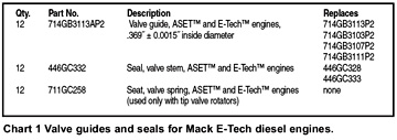
Beginning January 2006, valve guide p/n 714GB3113A was implemented into production. The proper service replacement valve guides are identified with a “P2” part number suffix. The service replacement “P2” guides are pre-reamed to a diameter that does not require an excessive amount of material to be removed when reamed to final size after the guides are installed. The inside diameter of the “non-P2” guides is smaller than the service replacement “P2” guides, making the inside diameter of the “non-P2” guide too small to be reamed with standard field service reamers. A summary of valve guide and seal part numbers is given in Chart 1.
Initial production of ASET™ AC, AI and AMI engines (approximately 200 engines prior to engine serial number 2J2355) utilized a unique-style valve guide and valve stem seal that must be serviced with components described in this bulletin. These early engines utilized a valve guide (714GB3107) having a tapered outside diameter near the top, and a seal which is attached to a steel retainer having an integral spring seat (seal assembly p/n 446GC333). If replacement of a valve stem seal on one of these early production ASET™ engines is required, it will be necessary to install the new guides (p/n 714GB3113AP2), seals (p/n 446GC332) and, ONLY if tip rotators are used, spring seats (p/n 711GC258). With E-Tech™ CCRS and pre-CCRS engines, the only serviceability issues include using the correct combinations of parts, using the correct installation tools and making sure to install the spring seat when replacing old with new. Old parts can be replaced with the new part numbers as long as both the valve guide and valve stem seal are replaced together, and the spring seat is installed if the engine is equipped with tip rotators. If tip rotators are being replaced, they are to be replaced with bottom rotators as described in AERA service bulletin TB 2246.


