Engine Builders: Maintaining oil drain intervals to those established by OEMs is always recommended because they know how each of their vehicles’ engines performs in the field. Always consult the owner’s manual for oil specification and drain interval.
Premium quality motor oil will maintain its effectiveness over the life of the drain without a significant drop in engine protection. Some key elements of motor oil and additive packages and the potential results of their depletion are detailed below:
Anti-wear additives lay down a protective, sacrificial film between moving parts, thus the additives are consumed during the life of the oil change. These additives also help stop oxidation of the motor oil which also causes them to be consumed. Changing the oil not only refreshes these additives it also removes dirt and other contaminates from the engine.
Dispersants grab dirt and sludge before they can build up during engine operation. As the oil absorbs more debris, it needs to be changed, or deposits will form. Changing the oil also helps prevent sludge deposits in the valve deck.
Detergents are consumed as they help keep high-temperature surfaces such as pistons clean. Changing the oil in proper intervals will help to prevent ring sticking and piston deposits.
Anti-oxidants stop oil oxidation and help keep the oil from becoming too thick. Properly functioning oil helps prevent loss of fuel economy, sludge and varnish deposits and helps maintain proper low-temperature pumpability.
Oil plays a major role in heat transfer in the engine. As oil ages and becomes thicker, it loses some of its ability to cool the engine. Changing the oil helps prevent piston deposits and helps cool moving parts.
Engines generate acids, which can cause corrosion. These acids eat at soft bearing surfaces and yellow metal used in bearings, oil coolers and other parts. Changing the oil helps keep corrosive wear to a minimum
Each engine consumes different parts of the oil at varying rates; therefore, it is not possible to establish a universal oil drain interval. It is always recommended that OEM drain intervals be followed. – Provided by Pennzoil
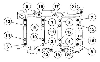
Engine Builders: The AERA Technical Committee offers the following information regarding the main bearing bedplate installation for 2001-2006 Ford 3.0L VIN 1 engines. This information should be considered any time the crankshaft is installed.
This engine uses 22 fasteners for the lower engine bedplate that also houses the lower main bearing shells. The bedplate assembly must be completely installed in and then removed to properly check main bearing clearance. Desired main bearing oil clearance is .0007"-.0018" (.018-.045 mm). There are three different standard bearings, as shown in the following chart, available to assist in achieving the desired oil clearance.
Stage 1) Torque fasteners 1-8 (small bolts) in sequence to 18 ft.lbs.
Stage 2) Torque fasteners 9-16 (large bolts) in sequence to 30 ft.lbs.
Stage 3) Rotate fasteners 1-16 (large and small bolts) in sequence an additional 90° turn.
Stage 4) Torque fasteners 17-22 in sequence to 18 ft.lbs.
It is suggested that oil clearances be set toward the "tighter" specification to achieve the required 45 psi @ 448 rpm (normal pressure reading).
Engine Builders: The AERA Technical Committee offers the following information regarding a coolant leak into the engine oil on 2002-2006 GM 4.8L and 5.3L VIN V, T, B & M engines. This leaking condition should be examined and coolant loss noted when cylinder head service is performed.
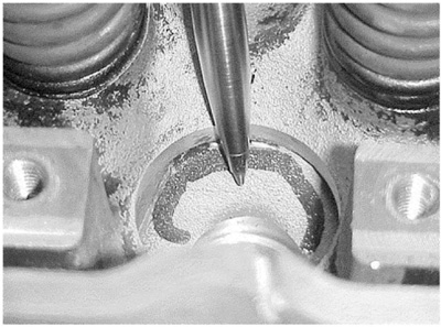
Two different locations on these engines have reportedly leaked coolant into the engine oil. A possible coolant leak may exist between the cylinder head valve guide bore and the interior of the cylinder head casting. Or a porosity condition may exist on certain Castech castings as shown in Figure 1. Under pressure while the cylinder head casting is hot, coolant may collect in the leaking areas of affected heads. If this leak is allowed to continue, eventual oil and coolant mixing will occur, and engine damage will result.
To determine if a cylinder head is manufactured by Castech, look in the inside corners for the company’s logo.
Engine Builders: The AERA Technical Committee offers the following information regarding a connecting rod caution for 1999-2006 Perkins 1004.42 diesel engines. This caution is to clarify that the proper connecting rod being used is the appropriate style for the service information.
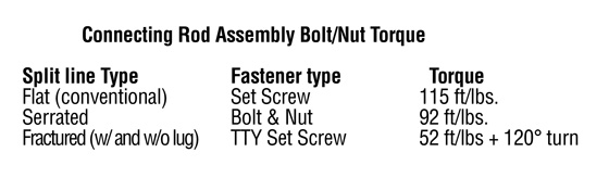
This engine uses four different connecting rod designs, two conventional 1040 steel rods and two "newer" Powdered Metal (PM) fractured rods. The steel rods came with a flat (smooth) split line mating surface and a serrated mating surface. The fractured rods come with and without locating lugs machined into the big end bores. There are several unique aspects that must be considered for each rod when servicing these rods.
There are as many as six different length rods available for some engines. They’re each marked with a letter code, with "F" being the longest and "L" being the shortest.
Fractured rods use a torque-to-yield (TTY) bolt and require bolt replacement any time they’ve been torqued to 50 ft.lbs + 120° and then loosened.
Fractured rods should be stored in an assembled state with the mounting bolts torqued to 15 ft.lbs.
Fractured rods and caps have an "A1"on the front face. Those markings must face the engine and piston front when assembled in the engine.
All 1000 series engines will eventually be built with either new style fractured connecting rod. There is an alignment tool supplied with rod bearings that do not have the locating lug. The tool aligns the bearing for and aft in the connecting rod big end bore.