The balance shaft procedure has been revised. Figure 4 has been added and the tightening specification in Figure 5 has been revised.
Balance Shaft Assembly
Tools Required:
• J 41 088 Balance Shaft Holder
• J 36660 Torque Angle Meter
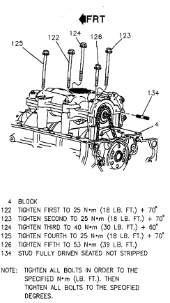
1. Balance shaft assembly to block. Use Loctite® 242 on the housing assembly to block bolts (122-126), refer to Figure 3. Use the following procedure if the balance shaft housing was disassembled:
• Loose assemble the housing assembly to the block. Tighten Housing to Block fasteners to 44 in.lbs. (5 N.m)
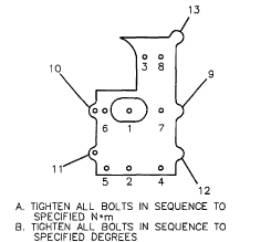
• Use the tightening sequence in Figure 1 to tighten housing fasteners and housing assembly to block bolts.
• Ensure that the balance shafts spin freely.
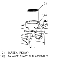
• Oil pump pick-up screen (121) into housing, refer to Figure 2. Lightly tap into place with a plastic hammer. If the balance shaft housing was NOT disassembled, use the tightening sequence in Figure 3.
Ensure the balance shafts spin freely. If the balance shafts are not properly timed to the engine, the engine may vibrate or make noise.
2. Time balance shaft to engine.
• Place #1 piston at TDC.
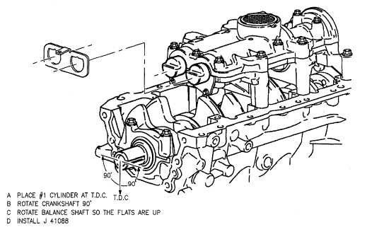
• Rotate the crankshaft 90° refer to Figure 4.
• Install J 41088 on to balance shaft assembly to ensure the shafts do not rotate while the driven sprocket bolt is tightened, refer to Figure 4.
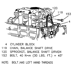
3. Driven sprocket (120) to shaft (132). The surface that was marked during disassembly of the driven sprocket must show if it is going to be reused. This will ensure that the chain continues to ride on the same surface. If a new driven sprocket will be installed, either surface can be placed against the shaft.
The balance shaft driven sprocket bolt is left hand threaded and must be tightened by rotating it in a counter-clockwise direction.
A NEW balance shaft driven sprocket bolt must be used any time the bolt is removed. If a new bolt is not used, the balance shaft sprocket may slip allowing the balance shafts to become mistimed and cause an engine vibration.
4. Balance shaft driven sprocket bolt (153) finger tight, refer to Figure 5.
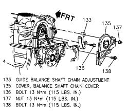
5. Install balance shaft chain guide, refer to Figure 6.
6. Press chain guide tightly against the chain.
7. Tighten chain tensioner fastener (136). Tighten bolt to 115 in.lbs. (13 N.m).
8. Tighten the balance shaft driven sprocket bolt, tighten bolt to 30 ft.lbs (40 N.m) plus rotate bolt 45°.
9. Remove tool J 41088 from balance shaft housing assembly.
10. Loosen balance shaft chain guide bolt (136) and adjust the
balance shaft drive chain tension. Balance shaft drive chain tension,
refer to Figure 7.
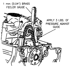
Adjust:
• Inserting a 1 mm (0.040?) BRASS feeler gage between the
chain guide and the chain. A brass feeler gage should be used to ensure
correct measurements are obtained. If a steel gage is used, it will not
bend to conform to the guide and cause incorrect measurements.
• Press the guide against the chain using about 3 lbs. of force.
• Tighten chain tensioner fastener (1 36). Tighten bolt to 115 in.lbs. (13 N.m).
11. Balance shaft chain cover (1 33), refer to Figure 6. Tighten nut and bolt to 115 in.lbs. (13 N.m).
Some or all of this information was provided by the Automotive
Parts Remanufacturers Association (APRA). For more information on
technical bulletins available through APRA call 703-968-2772 or visit www.AutoBulletins.com.