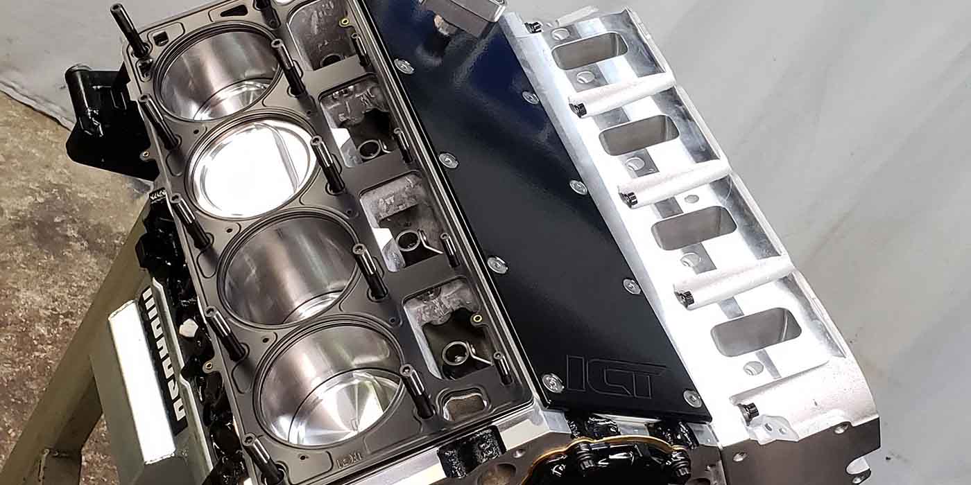
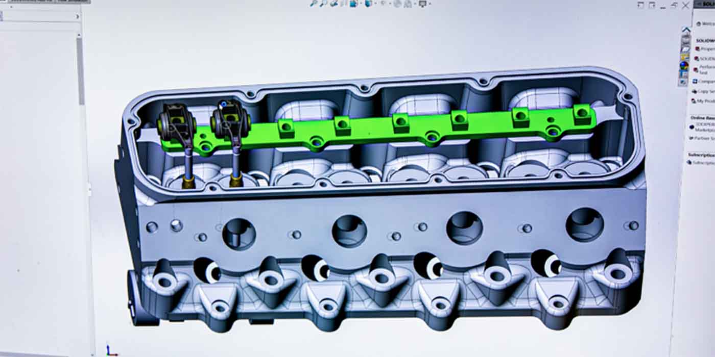
Valve springs are one of the most critical and most overlooked components in your engine.
Proper selection of the valve spring begins with identifying the
application and selecting all of the valve train components to achieve
the engine builders’ goals.
The
spring is selected to complement the system and must be matched with
the entire valve train in order for the engine to reach its full
potential. It does absolutely no good to install a cam that will rpm to
8,000 if you do not have the correct springs. Improper selection of the
wrong valve spring is one of the most common causes of engine failure.
Other common causes are the incorrect installation and improper
handling of the valve springs.
Selecting a Spring
1. Use only the valve springs that will give the correct spring
pressure with the valve both on the seat and at maximum lift.
2.
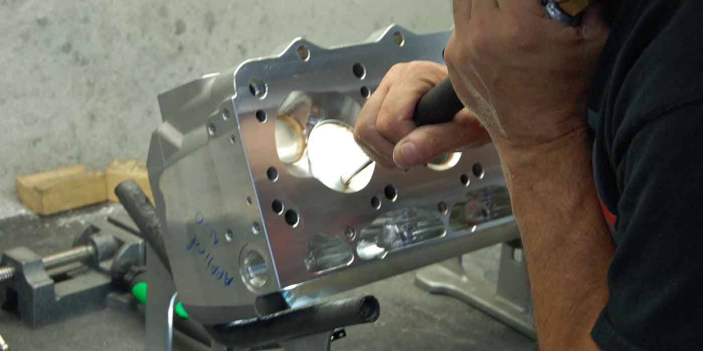
The outside diameter of the recommended valve spring may require that
the spring pocket of the head be machined to a bigger size.
3.
One of the easiest and sometimes most costly mistakes made in racing
engines is not positively locating the spring. A valve spring that
“dances” around on the cylinder head or retainer causes harmful
harmonics and excessive wear. A spring that is forced onto a retainer
is likely to fail at that coil. That is why suppliers carry such a large
selection of steel and titanium retainers, hardened
steel spring seat cups and I.D. locators to better match the
springs. A spring that is contained properly at the retainer and the
cylinder head will offer the longest possible service life.
Proper Spring Handling
1. Handle springs with care. Never place in a vise, grab with pliers or
hit them with a hammer. This will damage the surface of the spring,
which will cause a spring to fail.
When separating double or triple springs, use only a durable plastic
object that cannot harm the shot-peened surface of the spring. Never
use a tool or hard metal object like a screwdriver.
3.
Valve springs are shipped with a rust preventative coating that should
remain on the spring throughout engine assembly. Do not clean springs
with acidic or evaporative cleaners. This causes rapid drying and
promotes the formation of rust on the surface, which can cause
catastrophic failures. Even a slight amount of corrosion can grow to be
a problem.
4. When installing springs, use an assembly spray such as COMP Cams® Valve Train Assembly Spray to ease assembly and improve the life of the spring.
Checking Loads
1. COMP Cams has matched each set of springs for load consistency. A
variance of + or -10% is acceptable for new springs.
2.
When checking the spring loads on a load tester measure
and note the thickness of the retainer where the outer spring sits.
Assemble the retainer on the spring and place on the base of the spring
checker.
3.
Compress the spring to the desired installed height. This is the
measurement between the top of the spring (on the bottom side of the
retainer where the outer spring sits) and the bottom of the spring on
the base.
NOTE: Since the retainer is installed in the spring when checking the spring
loads, make certain that the thickness of the retainer is not included
when calculating the installed height and is accounted for when
compressing the spring. The spring load checker will show to be higher
with the spring installed at the correct height.
Installation
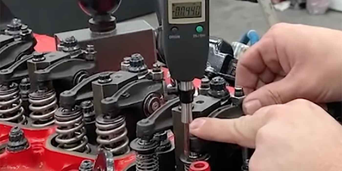
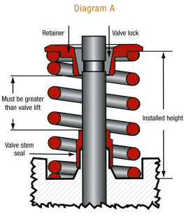
1. Before installing the spring on the cylinder heads, check the
installed spring height (Diagram A). This is the distance from the
bottom of the retainer to the surface where the spring rests on the
head. The valves, retainers and valve locks will be used in this step.
First, install the valve in the guide, then install the retainer and
valve locks. Pull the retainer tightly against the valve locks while
holding the valve assembly steady.
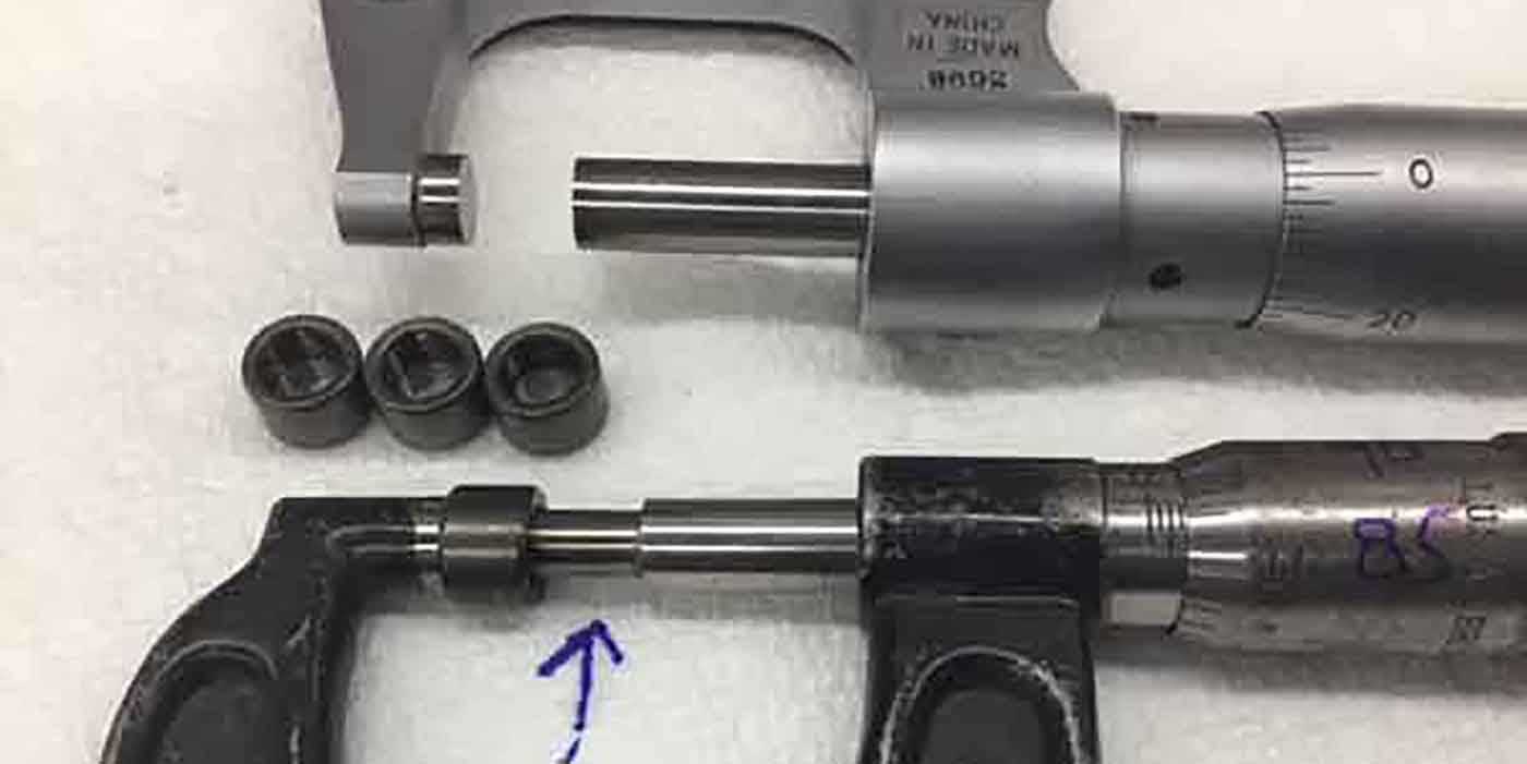
Measure the distance between the spring seat and the outside step of
the retainer using your height micrometer or a
snap gauge and a pair of calipers. Repeat this procedure for all the
valves and record your Information. After you have measured all the
valves, find the shortest height. This will become the spring’s
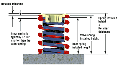
installed height on your heads. If your combination includes a dual or
triple spring assembly, it will be necessary to allow for the inner
steps of the retainer.
2.
Once you have determined the shortest installed height, it will be
necessary to use shims to obtain this height (±.020” is acceptable) on
the remaining valves.
3.
Before removing the retainers, measure the distance from the bottom of
the retainer to the top of the valve seal (Diagram B). This distance
must be greater than the lift of the valve. If not, the guide must be
machined. This is a very common cause of early camshaft failure.
4.
Once the valve springs have been installed, it is important to check
for coil bind. This means that when the valve is fully open, there must
be a minimum of .060? clearance between the coils of both the inner and
outer springs. If this clearance does not exist, you must change either
the retainer or the valve to gain more installed height, or change to a
spring that will handle more lift or machine the spring seat for extra
depth.
5.
Always check for clearance between the retainer and the inside face of
the rocker arm. This will be most evident while the valve is on the
seat. Rocker arms are designed to clear specific spring diameters, so
you should check to see that you have the proper rocker arm/retainer
combination. This situation can also be the result of improper rocker
geometry and may be corrected with different length pushrods or a
different
length valve.
6.
To aid in the engine break-in process, spray the springs, rocker arms
and pushrods with a valvetrain assembly lubricant.
Breaking In a Spring
1. It is important for new springs to take a heat-set. Never abuse or
run the engine at high rpm when the springs are new. Upon initial
start-up, limit rpm to 1,500 to 2,000 until the temperature has reached
operating levels. Shut off the engine and allow the springs to cool to
room temperature. This usually will eliminate early breakage and
prolong spring life. After the spring has been “broken-in”, it is
common for it to lose a slight amount of pressure. Once this initial
pressure loss occurs, the spring pressure should remain constant unless
the engine is abused and the spring becomes overstressed. Then the
springs must either be replaced or shimmed to the correct pressure.
– Tech Tip courtesy of Comp Cams.


