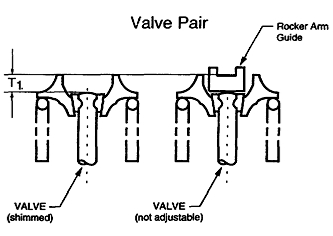
Each cylinder contains two intake valves and two exhaust valves. Each pair of valves is operated by one Y-shaped rocker arm. One valve in each pair contains a rocker arm guide which is not adjustable. The matching valve contains a replaceable shim. A hydraulic lash adjuster (HLA) is also included in the system and acts as the rocker arm pivot.
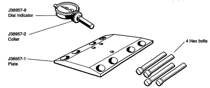
The main purpose of the shims is to match the height of the shimmed valve(s) to the height of the nonadjustable rocker arm guide. The HLAs zero the valve lash. The J38957-N kit consists of the following: See Figure 1.
The following procedure will ensure that the proper size shim is installed on the shimmed valve to achieve "zero" valve clearance.
1. Remove camshafts, rocker arms and shims. For future reference, identify each shim with the cylinder it was removed from. Since the shims are reusable, it may not be necessary to replace all of the existing shims.
2. Before attempting any measurement, make sure the valve, valve spring, collet, retainer and rocker arm guide are properly installed in the head.
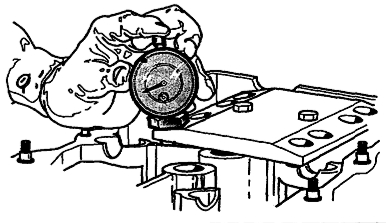
3. Install the J38957-1 gauge plate into the tapped holes at the cam journals and secure it to the head using two of the hex bolts supplied with the kit (see Figure 2). (The two remaining bolts are spares.)
4. Place the J38957-2 collar on the J38957-8 dial indicator. Make sure the dished side of the collar is facing "up" (toward the dial indicator). Secure the collar to the dial indicator by tightening the set screw in the collar.
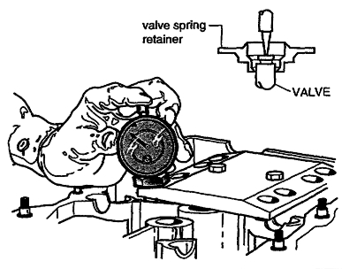
5. Place the indicator and collar over #1 cylinder intake valve, shim side. Slide the tip of the dial indicator through the access hole and place it on the end of the valve stem. While resting the dial indicator collar on the gauge plate, "zero" the dial indicator (see Figure 3).
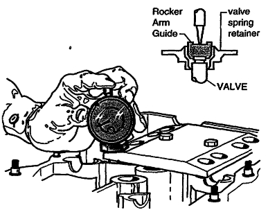
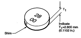
6. Move the dial indicator and collar to the adjacent hole in the gauge plate and place the tip of the indicator in the center of the rocker arm a. Write down the did indicator reading. This measured distance between the valve stem end and the contact surface of the rocker arm guide is the "T1" dimension (see Figures 4 and 6).
7. Match the measured "T1" dimension (in inches) to the available shim chart (in millimeters) located in the S.D.S. section of the appropriate service manual. (The "T1" dimension is equivalent to the thickness and size designation of the valve shim.) Select the closest size shim to the measured "T1" dimension. For example, if the measured "T1" dimension is .1154? use a 2.925 mm shim. Shims are available in 17 different thicknesses ranging from .110? (2.800 mm) to .126? (3.200 mm) and increase in increments of .001? (.025 mm). (See Figure 5).
8. Repeat this procedure on the remaining cylinders.
Some or all of this information was provided by the Automotive
Parts Remanufacturers Association (APRA). For more information on
technical bulletins available through APRA call 703-968-2772 or visit www.AutoBulletins.com.