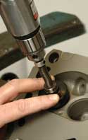
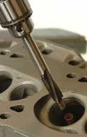
The first step for installing bronze guide liners is to assemble the parts for the boring reamer. Install the bushing, then the spring, and finally the retainer. You now have a reamer kit. Insert the reamer kit in an air/electric drill. The proper drill should not exceed 1,000 rpm under load. Next, choose the appropriate 60° seat collar for your application and install it on the reamer bushing. Insert the reamer pilot into the valve guide to be bored, and hold the seat collar down on the valve seat.
Note: Cast iron guides are bored dry.
Raise the boring reamer off the valve guide slightly, start the air drill, and bore the valve guide. Boring time should be 5 seconds or less.
If you hear a “rumble” during the operation, this is “chatter”. To eliminate chatter, just push a little harder. Bore all guides, and blow away the chips.
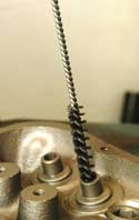
Once all the guides are bored oversize, turn the cylinder head over so the “spring side” is up. “WET BRUSH” each bored guide with a nylon brush and a lube (Cutting & Tapping Fluid works well). Spray the brush approximately 1 second and clean each guide. Repeat for each guide.
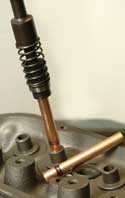
Insert the auto-driver in a “short stroke” pneumatic hammer (more than 3000 blows per minute, and set the regulator to about one-half power. Insert a bronze-liner on the auto-driver so that the “Speed-Lead” end will be inserted into the guide first, then install.
Note: The auto-driver will install the bronze-liner “FLUSH”. This operation should take between 3-5 seconds.
If you have chosen a bronze-liner that is longer than your application, the excess length will be protruding from other side and must be trimmed off. This operation is generally performed after the sizing operation, as the bronze-liner will grow slightly.
Caution: Distortion will occur on the bronze-liner if too much power is used during the installation operation. This will make the sizing operation difficult.
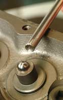
Using the carbide sizing ball install the ball driver into a “short-stroke” pneumatic hammer and adjust the power to about one-half. Select a carbide sizing ball .001? larger than the desired finished size and set it on top of the guide. With the pneumatic hammer in one hand, use your other hand to hold the tip of the driver with your finger and thumb. Then, with slight down pressure, start driving the ball. Once the driver tip is inside the guide, release the driver with your fingers and move your hand under the cylinder head and catch the ball when it comes out of the guide.
Note: Before sizing the next guide, trim the first one to length and check the “fit,” using the appropriate size valve. Use a larger ball, if necessary, and repeat the process. When the desired size is achieved, size the remainder of the guides.
We suggest having several different sizing balls on hand, as there will always be a fluctuation in valve stem dimensions. After all the guides have been sized, the excess length must be trimmed off.
To trim, insert the appropriate pilot into the trimming tool. Install the trimming tool into a 500 rpm air drill, and trim off any excess material. If a “burr” is created during this operation, it can be removed with the chamfer tool that has been installed in a “T” handle.
As a final step prior to assembly, it is recommended that the bronze-liner be brush-honed. This increases the surface finish, which gives the guide greater oil retention.
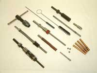
Note: A Master Tool Kit contains everything you’ll need to install bronze-liners. They are dimensionally correct and sized to match the
most common guide sizes. Kits include: 3-Carbide sizing balls, ball
driver, carbide reamer, reamer bushing kit, auto-driver, removal tool,
removal tool driver, trim tool, trim tool pilot, chamfer tool,
T-wrench, flex-hone and guide brush.
–Tech Tip courtesy of Goodson Tools and Supplies.