Based upon some of
the questions that I have been getting lately – particularly in the
areas of valve train lifter noise and bearing clearances – I thought it
was time to go back to engine school.
Let’s take a quick run through Hydraulic Lifter 101 and at the end I’ll
leave you with a valuable PBT (Practical Builder Tip). There are, of
course, a number of different hydraulic lifter forms today. The most
popular are flat lifters and roller lifters, both typically seen in
overhead valve engines. The latest technology is Displacement on Demand
(DOD) or whatever buzzword each manufacturer has come up with for
having an electronically controlled oil manifold that can shut oil on
and off to different lifters and thus deactivating cylinders.
The bottom line is that all hydraulic assemblies are going to operate
on the same basic principle. When on the base circle of the camshaft
the plunger spring takes up the clearance in the valve train. Oil under
pressure will enter the body of the hydraulic unit through an orifice
of some type to feed the plunger. The oil will then pass through the
plunger past the check valve and fill the void below it. As the
camshaft rotates and the lobe ramp and lift takes place the pressure of
the valve train weight and valve
spring pressure apply load against the oil below the check valve which
forces it to seat and in essence becomes a solid unit. A metered amount
of oil does pass between the plunger and body and that is the
controlled leakdown. Once the valve opens and closes we are at the base
circle and the entire cycle starts all over again (see Figure 1).
Now for the PBT. Every hydraulic unit of any type in an internal
combustion engine has the same optimum operating range; the center
third of its total travel. So if you have a flat hydraulic lifter that
typically will have .210" travel your optimum operating range is
.070"-.140" (.210/3=.070). However if you have a HLC with a travel
range of .045" your optimum operating range is .015"-.030". Are you
starting to see where I am going with this?
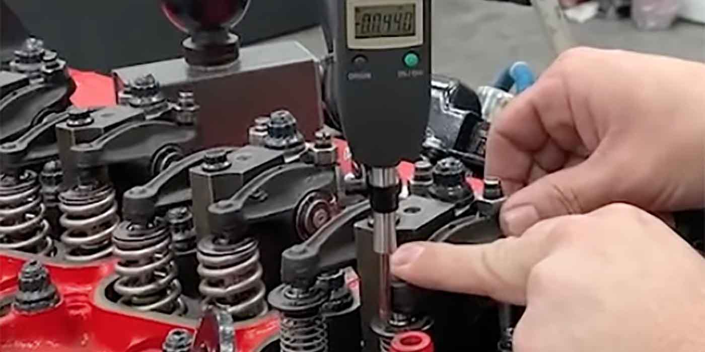
What controls whether your lifter is in the operating range? Valve stem
height! So if you only have a .015" window of optimum range in your HLC
but you have a valve stem height spec range of .030" what do you think
is going to happen?
Coupled with the fact that very few OE manufacturers provide a
maximum/minimum stem height spec you are at the mercy of what is
alleged to be the correct information. Do not take everything that you
find out there to be true and correct. Verify dry lash before deciding
that a problem you have is a component failure – it may actually be a
bad specification.
Unless you verify the correct information (I strongly recommend
recording it for future use) you could be building your own problems
into an engine and not even know it. Stem height that’s too low can
result in a clattering valve train and stem height that’s too high can
result in a lifter that pumps up and holds the valve open resulting in
a miss and/or misfire code. Neither of these are going to make you
happy.
Now on to bearing clearance. The good thing is that this is a
specification that is readily available from the OE manufactures.
However, remember that they operate with new components that are all
standard and have the option of select fit bearings that allow them to
adjust for any variances in either housing bore or shaft diameter. As
the builder/reman, you are going to be using under/oversize machined
components. They can all be to specification tolerances but may still
render unsatisfactory results for maximum bearing oil clearance.
Say for instance you have line honed a block and the main bearing
housing bore is at the low limit of tolerance. You have a crankshaft
that is reground and the main bearing journals are at the high limit of
tolerance. You are seeking .0015-.002" vertical oil clearance.
Prior to installing the crankshaft you install the main bearings in the
block with main saddles torqued to spec and use a dial bore set to the
crankshaft size and find that you have .003" to .0032" vertical oil
clearance. Not nightmarish, but certainly more than what you want and,
as it turns out, beyond maximum specification. You remove the main
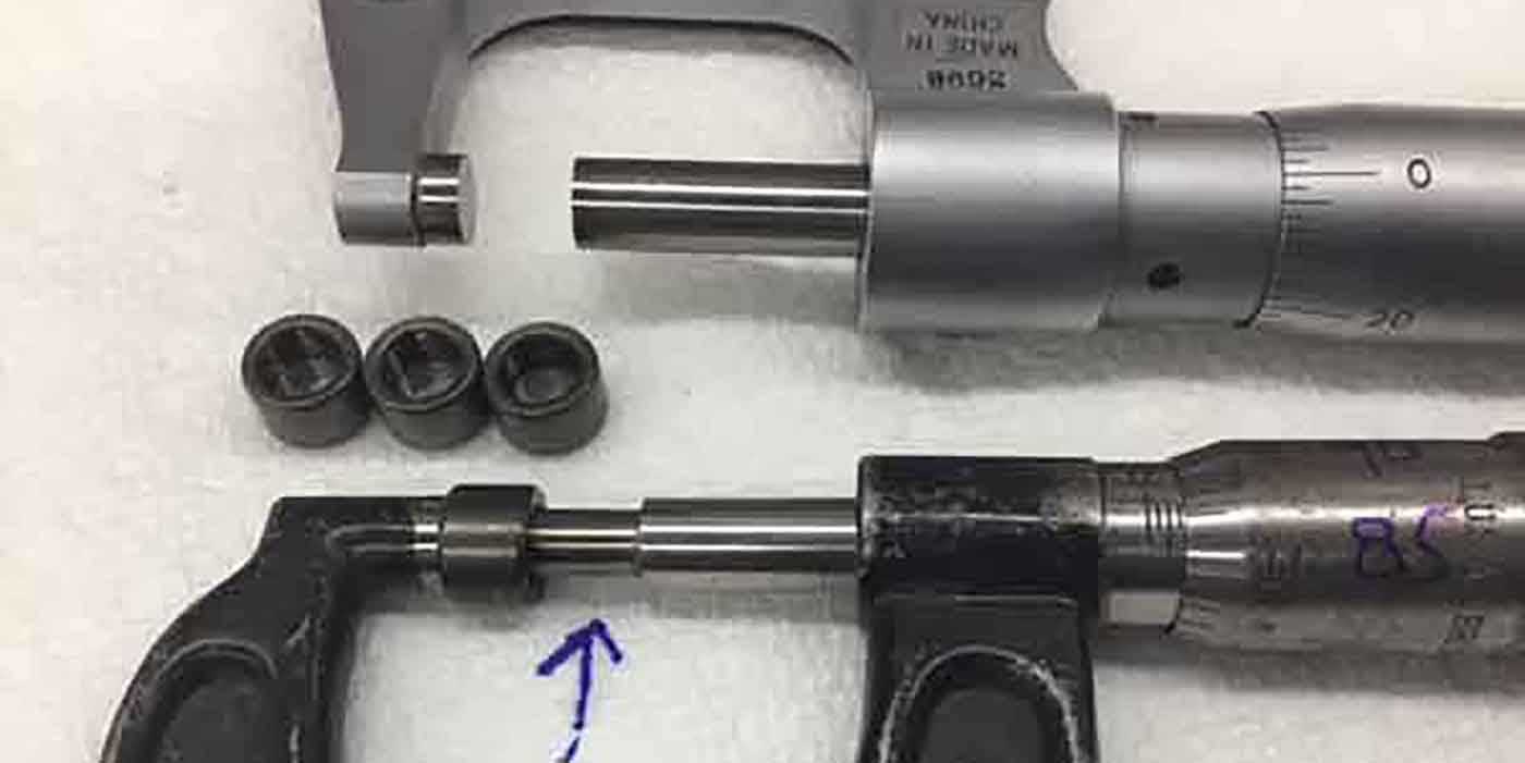
bearing and use a ball micrometer and find that bearings are .0005"
smaller than the maximum wall thickness listed at the crown.
You get another bearing set and another, try three different
manufacturers and find that they are all consistent in thickness. Now
if you lose .0005" per bearing shell that is .001" in clearance and if
you took away .001" you would be perfect.
The quandary? Deciding what is going to be an acceptable scenario and
not cause damage. You could make the main bearing housing bore .001"
smaller but then you need to worry about bearing crush being excessive.
Since you have tried three different bearing manufacturers with the
same result, I consider the only logical solution is to grind the
crankshaft beyond the maximum specification to render the correct
clearance. Sometimes being wrong is the right thing to do.
I also propose that some of these scenarios may actually be a
conversion factor between metric and standard dimensional measurement.
The conversion factor is .03937 but no one generally goes that far out
in a conversion. For instance .25 mm is considered .010" undersize yet
if you convert .25 mm it comes out to .0098425" and .50 mm is actually
.0019685" and .75 mm is .0295275". You can see that when you get out to
.75mm or .030" you are almost a full half thousands off dimensionally.
If you convert .030" to a pure metric size it comes to .07620 mm. I
know that nothing is going to change and if you talk to bearing
manufacturers they will tell you that they have compensated…but which
way?
All I am saying is that out in the real world there are instances
particularly in main bearing clearance that end up being excessive
which can result in low hot idle oil pressure or worse a hot idle main
knock.
I am not trying to cry wolf and be an alarmist but today’s engines are
operating under higher cylinder pressures and trace detonation. Higher
temperatures and more horsepower with smaller displacement. The luxury
of wider tolerance ranges in many of today’s engines does not exist and
you either have it right or you are out of the game. I hope that these
two situations keep you aware of what can happen and that sometimes
thinking out side the box is what you have to do today if you’re going
to be successful.


