These items are:
• A large Degree Wheel, such as LUNATI CAMS P/N 80000
• A Dial Indicator & Magnetic Base Stand, such as LUNATI CAMS P/N 80012
• A Steel Deck Strap Kit, such as LUNATI CAMS P/N 80013
• All of the above is available as LUNATI CAMS DEGREE WHEEL KIT, P/N 80001
• Some suitable pointer (made from coat hanger wire, paper clip, etc.) rigidly attached to the block
1. The first step is to install your new camshaft and line up the stock timing marks.
2. To begin the actual degreeing procedure, the degree wheel should be attached to the front of the crankshaft. A pointer of some type such as a piece of wire should be secured to the front of the engine. The engine should be capable of turning in either direction. Use a crank socket or other suitable tool to rotate the engine. At this point you will leave the wheel somewhat loose.
3. Rotate the crankshaft until the number one piston is at approximate Top Dead Center and align the pointer with TDC on the degree wheel. Tighten the wheel.
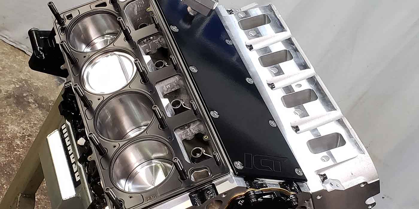
4. The next step is to find true Top Dead Center (TDC). The most accurate method is to secure a flat strap (1-1/2 x 1) that will bridge the bore (with the heads removed). A Steel Deck Strap Kit is included in the Lunati Degree Wheel Kit, or is available separately (P/N 80013). (If the heads are on the engine, another method of finding TDC is necessary. This method uses an old, discarded sparkplug. Remove the porcelain and use a tap, 3/8" 24NF, to cut threads through the plug. Insert a Bolt so that it will protrude through the plug approximately one inch. Remove the rocker arms and push-rods so the valves will not be bent.
5. Rotate the engine clockwise until the piston contacts the stop. At this point you should mark the degree wheel.
6. Next, rotate the engine counterclockwise until the piston contacts the stop again. Make another mark on the degree wheel. If the degree wheel is properly located, the marks will be an equal number of degrees on both sides of TDC. If not, the degree wheel will have to be relocated. For example, if you come up with 34 degrees on one side and 30 degrees on the other side, the wheel will have to be rotated 2 degrees to compensate for the misalignment. After the wheel has been relocated, the piston should hit the stop the same number of degrees on either side of TDC. After TDC has been found, remove the piston stop to allow complete engine rotation.
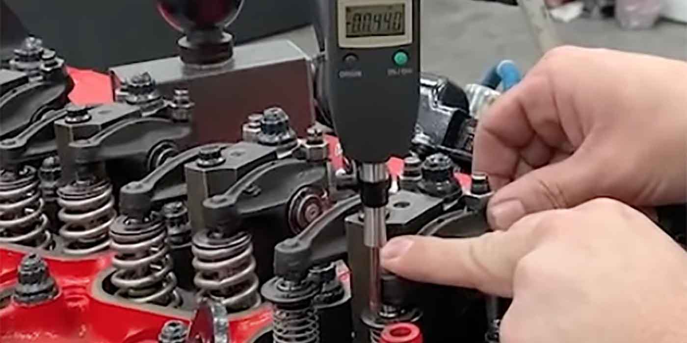
7. Install the lifter in the number one intake lifter bore. Use a mechanical lifter for flat tappet grinds and a roller tappet if the cam is a roller grind. The indicator must be positioned securely above the lifter. The stem from the dial indicator should be aligned with the lifter as close as possible. Misalignment will cause an improper reading. Rotate the engine at least two revolutions. Make sure the dial indicator is working freely and the lifter is not sticking or binding in the bore, and that you have adequate indicator travel. Rotate the engine clockwise until the lifter is on the heel, or base circle of the cam lobe (minimum lift). Zero the dial indicator.
8. Rotate the engine in clockwise direction until a 0.050" reading is reached.
9. Rotate the engine in clockwise direction until a 0.050" reading is reached. View the degree wheel at this time. This point is 0.050" of lift on the opening side of the intake lobe before top dead center.
10. Compare the reading on the degree wheel with the "IN OPENS" specification on the cam card. If it does not match, your cam is either retarded or advanced. For example, if the degree wheel reading at 0.050" comes up 10 degrees before top dead center (BTDC), and your P/N 00010 cam card lists the 0.050" intake opening at 8 degrees, your cam is 2 degrees advanced. If the degree wheel reads less than 8 degrees, your cam is retarded. If either is the case, proceed to step 11. If it matches, your cam is installed as designed.
11. So, what do you do if your 0.050" opening lift point doesn’t match the cam card (or you wantto set your cam timing to something other than the cam card specifications)? There are several methods to adjust the valve timing:
• Degree bushings can be used on the cam sprocket to offset the cam locating pin.
• 3- or 9- keyway timing chain sets have additional keyways cut into them to index the crank sprocket.
After you have adjusted your cam using one of the previous methods, go back to step 10.
– Tech Tip courtesy of Lunati 


