Note: New lifters must be installed with your new camshaft prior to Installation:
• Check the compatibility of the camshaft with the remainder of the valve train components (valve springs, rockers, etc.)
• On race type, high spring load applications, use lighter load springs or remove the inner spring (dual spring application) just for break-in.
As a point of interest, the most critical time in the life of a flat tappet camshaft is the first 20 minutes of break-in during which the bottoms of the lifters “mate-in” with the cam lobes.
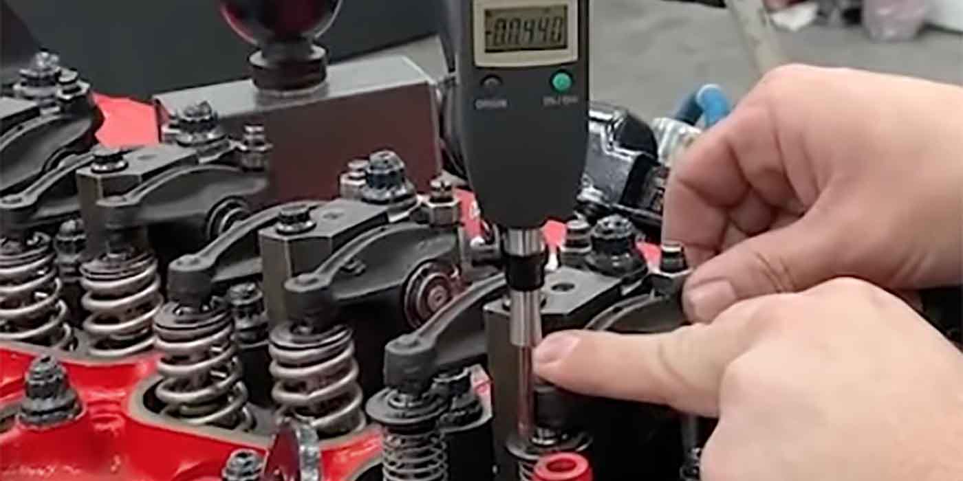
There are some oils with additive packages that are better for camshaft break-in. These include, but are not limited to: Brad Penn or Joe Gibbs racing or a race only petroleum-based oil, also include a lube/ZDDP additive (available from suppliers such as Crane Cams p/n 99003-1). Do not use API rated SL, SM, or SN oil.
Use of synthetic oils is not recommend for break-in. Prior to installing the camshaft and lifters, it is recommended that the crankcase be drained and filled with new, clean oil as listed above. The oil filter should also be changed at this time. Proper flat tappet camshaft break-in starts with the cam installation and includes the following steps:
1. Before installing the camshaft and lifters, wash them thoroughly in clean mineral spirits to remove the rust preventative that is placed on the cam before shipping.
2. DO NOT “pump-up” hydraulic lifters before use. This can cause the lifters to hold a valve open during engine cranking, which will cause low compression. The low compression will delay engine start-up and is very detrimental to proper camshaft break-in.
3. Use a moly paste lube (supplied by manufacturer) to coat the bottom of the lifters, cam lobes and distributor gear. Use an assembly lube on all other surfaces and components (such as Crane Cams p/n 99008-1).
4. Set your valve lash or lifter preload. Try to minimize the number of times that you rotate the engine, as this can displace the moly paste from the lobes and lifters.
5. If possible, prime the oiling system. When priming, rotate the engine at least two complete revolutions to assure oil gets to all valve train components. Valve covers should be off to assure that all rockers are oiling.
6. Preset the ignition timing to start the engine at a fast idle. It is important that the static ignition timing is set as close as possible and if the engine has a carburetor, it should be filled with fuel. The engine needs to start quickly without excessive cranking to insure immediate lubrication to the cam lobes.
7. Start the engine and immediately bring to 3,000 rpm. Timing should be adjusted, as quickly as possible, to reduce excessive heat or load during break-in. Get the engine running fairly smooth and vary the engine speed from 1,500-3,000 rpm in a slow, to moderate, acceleration/deceleration cycle. During this time, be sure to check for any leaks and check out any unusual noises. If something doesn’t sound right, shut the engine off and check out the source of the noise. Upon restart, resume the high idle speed cycling. Continue the varying break-in speed for 20-30 minutes. This is necessary to provide proper lifter rotation to properly mate each lifter to its lobe. Should the engine need to be shut down for any reason, upon re-start it should be immediately brought back to 3,000 rpm and the break-in continued for a total run time of 20-30 minutes.
8. Let the engine cool, and then drain the crankcase and properly dispose of the oil and oil filter. Refill the crankcase with a premium petroleum-based oil that contains the flat tappet compatible additives, not a synthetic oil. At this point the initial break-in is complete. The engine can be run normally. It is recommended that you change the oil and filter after 500 miles. You might want to put another 5,000 miles on the cam before switching to a synthetic, if that is your preference.
Additional Information:
Spring Pressures: For extended camshaft life, flat-tappet cams should not be run with more than the recommended open valve spring pressure. Racing applications will often need to run more spring pressure at the expense of reduced camshaft life. In order to break-in a camshaft with high open pressures, the inner springs should be removed to reduce break-in load. The inner springs can then be reinstalled after initial break-in is complete.
Lifter Rotation: Flat tappet cams (both hydraulic end mechanical) have the lobes ground on a slight taper and the lifters appear to sit offset from the lobe centerline.This will induce a rotation of the lifter on the lobe.This rotation draws oil to the mating surface between the lifter and the lobe. If it is possible to view the pushrods during break-in, they should be spinning as an indication that the lifter is spinning. If you don’t see a pushrod spinning, immediately stop the engine and find the cause.
Never use old flat tappet lifters on a new cam. On flat tappet cams, the lobes and lifter bottoms mate together. if the lifters are removed from the engine, they must go back on the same lobe from which they were removed. Crane Cams recommends the use of high quality lifters to prevent premature cam or lifter wear.
Big Block Chevrolets have an oil-priming idiosyncrasy. When priming a Big Block Chevy with a drill motor and priming tool, it is often necessary to prime for as long as 20 minutes (while rotating the engine.) to get oil to all of the lifters and rockers. It is advisable to prime these engines with the valve covers removed so you can check to see oil coming out of all of the rocker arms before firing the engine. This last step is advisable on all engines, but particularly on Big Block Chevrolets.

–Courtesy of Crane Cams


