I’m speaking of cam bearings, particularly those in OHV engine
applications. What brought this to my attention was what I would call a
“textbook” case of cam bearing oil bleed-out that caused the rod
bearings to fail. Don’t follow me? I’m not surprised. I’m certain many
of you may be scratching your heads wondering what I mean by that.
Let’s talk cam bearings. Many cam bearings have been manufactured
with a lining of babbitt, a soft, slippery face material. As a bearing
layer, babbitt possesses the best of all worlds for a bearing: it has
great embedability for particle contaminants, will tolerate minor
misalignment of housing bores and is an excellent surface for marginal
lubrication upon start up. Babbitt will also tolerate “wear in” (for
lack of a better explanation, it will push itself around to create its
own clearance).
In short, it’s the perfect material for cam bearings, especially a
“light tight” full round bearing. The downside is its relatively low
strength, and we will get into that a bit later. Optimum cam bearing
clearance should be in the .002?-.003? range, but that number may go as
high as .004? in certain applications but still be tolerable. Get too
much above that and you will see premature cam bearing wear.
Installing semi-finished cam bearings and boring them for alignment
and clearance is a practice that is typical to most OE’s and some
remans but for much of the real world and almost all rebuilder shops a
more likely scenario is use of a “pre-fit” cam bearing set. Each
individual bearing is driven into its respective bore and clearance
should be correct. Now, we are making the assumption here that the
lead-in edge of the bore in the block has proper chamfer, the bearing
has been driven straight and true and the housing bores are in
alignment. Each of these factors, if not correct, will lead to
premature cam bearing failure.
Another contributing factor to cam bearing failure may be the lack
of surface contact on the OD. More and more blocks are cast with full
circle oil grooves, which diminish a lot of the contact surface area on
the OD of the cam bearing. If you have a bearing that is light press
fit into a block and 30 percent of the contact area is now an open
groove for oil flow you can see how that may present a dilemma, both
from an installation and retention standpoint.
In an effort to account for all of these factors the cam bearing ID may
actually be at the maximum clearance or even slightly beyond. This is
where the trouble lies. If you start out at the max bearing clearance
how long will it be until it wears beyond and causes a premature engine
failure? In particular, this is a problem with rod bearings.
As a case in point, the photos accompanying this column are from a
2.2L Chevy engine. Millions of these motors have been produced and you
probably see them in your facility on a regular basis for reman. This
engine had about 15,000 miles on it and came in with a rod knock due to
all four rod bearings being worn down to the copper layer. This is
typical of what you would see with an oil starvation situation (see Figure 1).
However, notice in Figure 2 that the lower rod
bearing (non-load side of the bearing) is still intact with little or
no bearing wear and the main bearings are in good condition as well.
While trying to determine the cause of this premature engine failure
it was noticed that the cam bearings had abnormal wear on the loaded
side of the bearing (see Figure 3).
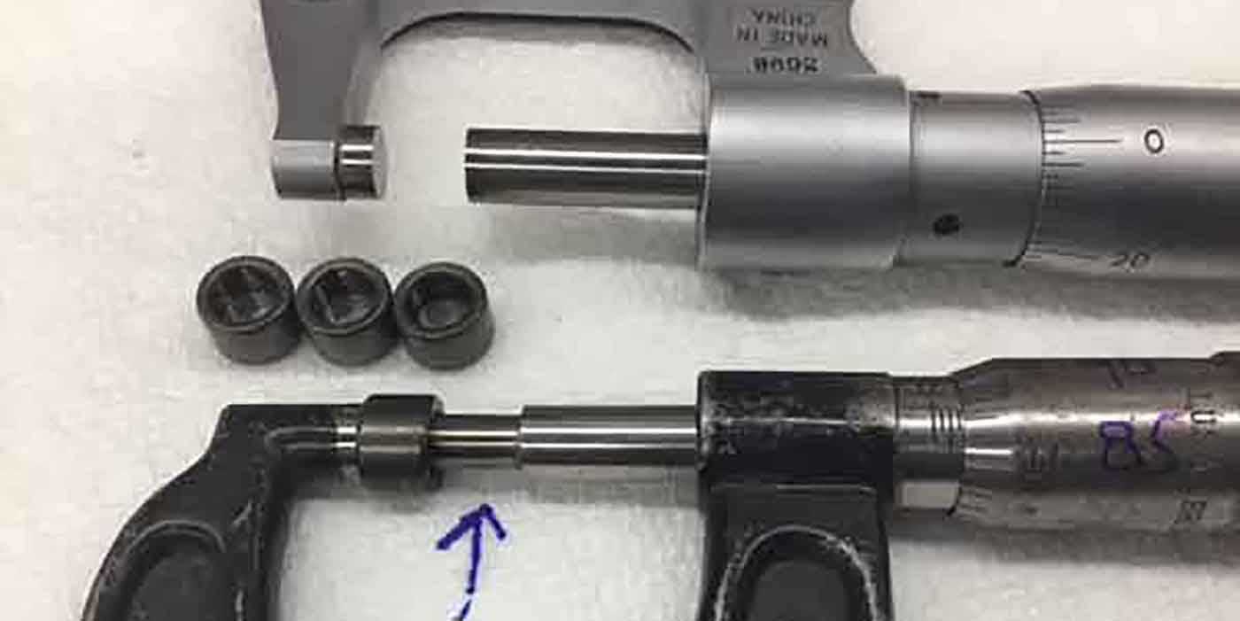
Once a dial bore was installed into the cam bearing the non-worn area
measured about .005? oil clearance, while the darker shaded area in
Figure 3 measured .015? clearance, an obvious oil bleed-out point. All
of the cam bearings were measuring in the same manner. So with the oil
flow feeding the main bearings first, the cam bearings then fed off the
mains through the block and the rods, which were fed from the mains
through the crank.
So the rods got the least amount of oil. The combustion pressures were
then able to break down the deficient oil film of the rod bearings,
resulting in the premature bearing wear. This engine was dramatically
close to taking out the journals completely and having a catastrophic
failure.
Upon further review of the standard bearing for this application it
was found that bearing clearance would typically exceed the optimal.
However, clearance with the .002? undersize bearing that is available
for this engine was perfect. It did not matter what bearing brand was
used; they all gave the same result.
The moral of the story is don’t take anything for granted. What may
seem to be correct under normal circumstances may not actually be
optimal, and if you build it, they will come – to your front door if
there is a problem.
So out of all of this is don’t assume that,
if your block cam bearing housing bore is on size and you have
installed everything correctly, the clearance is perfect because it may
not be.
Going forward there may also be other options besides the undersize
ID cam bearing. As today’s engines are developed or refined, their
limits will be pushed to develop more horsepower, torque and fuel
efficiency. With these gains comes an increased load on the internal
parts of the engine, not to mention the increase in temperature.
Getting taxed dramatically under these conditions are the cam bearings,
that vital link along the path of the oiling system.
You’ve already seen the evidence of what can happen if a cam bearing
wears prematurely. Other problems related to this situation are
excessive cam lobe runout, improper timing and general poor running
conditions.
Many bearing manufacturers are now offering and moving to replacing the
babbitt-style bearing with an aluminum alloy. Babbitt load pressure
tolerance is around 1,800 psi where the aluminum alloy bearing is up
around 5,000 psi. This is quite a difference, but isn’t necessarily the
cure for all the ills. The aluminum alloy presents its own challenge
especially with oiling, so you will see this style bearing with more
oil feed holes, or a full groove on the ID but that is another story
all in itself.
Just because it’s new does not always mean that it will render the
tolerances that you desire. As always you need to make certain that
what you build is right and correct because it is you who has to stand
behind it. So you may want to take another look at cam bearings and
their final ID dimensions because it might not be what you expect.
Instead, it could be the root cause of failures that you never
realized, because it was a catastrophic failure before it got back to
you.
Roy Berndt has decades of machine shop experience.
He is the Program Manager for PROFormance
Powertrain Products, a PER in Springfield, MO. You can reach Roy at [email protected].


