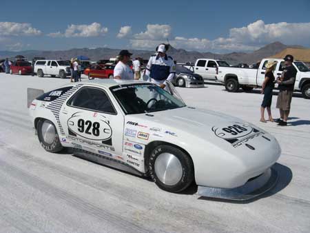
We would build for the Blown Gas Modified Sports (BGMS) class where the record is currently 231.5 mph. Another record we were after was the Porsche marquee record for the 928 of 205.6 mph.
Our math told us that – because we knew our final drive ratio, tire diameters and engine redline; and if our estimates for vehicle frontal area and coefficient of drag were correct – we would need 750 hp at the tire just to meet the current record. With a 15% drivetrain loss, this meant we would require 900 hp at the engine to net the 750 we needed at the tire. (Remember, the class is Blown Gas Modified Sports cars – there is a “Fuel” class as well and they get to run anything they want in their tanks such as alcohol, nitro methane or whatever.)
Cars in the Gas class must run the event gas provided – everybody gets the same event gas right there at trackside and then your filler neck is sealed by the officials. Using just straight gas, making 900 hp from this small V8 would be a little more challenging. Also, we didn’t have to make 900 hp once, but repeatedly and for a long time. Unlike a dyno pull of 6 seconds or so, we would be at wide-open throttle and full load for almost 2 minutes each run – and have to do that several times to get our Bonneville 200 mph license and (hopefully) establish a new world record. The stresses on the engine during these runs are staggering.
Over the last decade I have carefully modified and built each engine in my race car and have learned the “do’s and don’ts” peculiar to supercharging the Porsche 928 engine. I had already built a 650 hp motor for my race car and it had performed admirably at the Pikes Peak International Hill Climb where it netted us a podium finish in the Open Division and made us the fastest 2WD car in the class.
But for Bonneville, 650 hp wasn’t going to get it done. Every system in the engine would need attention if we were to make the hp needed and survive long enough to repeat it. Some of the parts I would need existed, but had to be adapted or modified to the task. Many others didn’t exist at all and would have to be engineered and fabricated from scratch.
Compression Ratio and Displacement
When designing the engine for this event, I had a choice of displacement options and compression ratios. The displacement decision was made easy by looking at the current Bonneville land speed records. The engine size with the lowest mph record was the lowest hanging fruit on the tree, so we felt it was ripe for a change. This meant I would build for the “B” engine class – engines from 6.11L to a maximum of 7.19L. By boring and stroking the 928 it landed squarely in the middle of the “B” engine class at 6.54L.
Compression ratio is another matter. When building for boost there are two schools of thought: build with higher compression and run low boost, or build with lower compression and run higher boost. In theory, both engines can produce about the same horsepower, but I am a member of the group that believes that the lower CR motor will be safer and less difficult to tune.
With lower compression, I have a larger cylinder volume to fill with air/fuel mixture, a safer burn, and (arguably) higher outputs. We decided on a 8.5:1 compression ratio, and about 15 to 18 psi of boost. The custom pistons were made for us with molybdenum coated skirts and ceramic crowns.
Doing the Math
After a little engine math we learned that 900 hp would require the capacity to move 320 cfm into each cylinder and 260 cfm out at ambient pressure (1 bar); or an average of 2,560 cfm for the complete V8 engine. Then, if we ran about 2 bar of manifold pressure, we should hit our numbers.
I began at the combustion chamber and worked outward from that point on every component and system all the way to the air filter on the intake side and to the exhaust tips on the other. Every part of every system had to have as much capacity as the next and none less than 2,560 cfm.
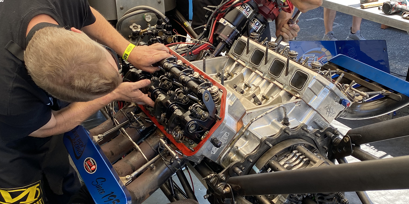
Cylinder Heads
Usually, porting a set of heads is up to the skill of the tool operator as each intake and exhaust port is hand-milled to open them up. In many cases, this is the only way it can be done. But no matter how expert the operator, making the intake and exhaust ports match from cylinder-to-cylinder is just about impossible. And with that irregularity, variables from cylinder-to-cylinder are being built in that will negatively affect the engine’s smoothness, power and longevity under high loads.
To get more cylinder-to-cylinder consistency, we developed a CNC milling program on a 5-axis mill for optimizing the 928 heads. This digital milling process guarantees not only maximum flow, but repeatability from cylinder-to-cylinder.
Valve Sizes and Seats
In concert with our CNC porting job, we upgraded from stock 36 mm to special 39.5 mm intake valves, and also larger 33 mm exhaust valves. We opted for stainless steel as the material for our valves which allowed us to have the same valve weight as stock, even though the valves were larger. Titanium is also available for high-rev engines but we didn’t think we needed it as we would be staying under 7,000 rpm. Special beryllium-copper valve seats were used to improve the thermal conductivity of the seat and to reduce valve bounce at closing.
Valve Springs
At 15 pounds of boost, our 65.2 gram intake valve with a head diameter of 1.899 sq.in. will have a virtual weight (physical weight plus air pressure loading) of 28.63 pounds. This meant stronger springs were required to close the intake against the boost pressure. Other challenges also included controlling valve float from cam lobe toss and seat bounce at 7,000 rpm, yet avoid valve spring stack with our high-lift (.442?) camshafts.
The solution was a custom set of valve springs made from chrome-vanadium wire, shot-peened, heat-treated and stress-relieved. Titanium retainers and clips were found and used to hold them in place.
Camshafts
Of course the large valves and porting alone won’t move the right amount of air without the cams to lift them. Unique to the Bonneville application, we needed our max hp to come in at 7,000 rpm where we will have our greatest aerodynamic resistance. A combination of special cams and intake runner lengths were used to tune the power band to make this happen.
Here we have a certain disadvantage compared to our friends running pushrod motors. Because a pushrod motor can use a 1.4:1, 1.5:1 or even 1.6:1 rocker arm ratio, they can throw their valves open further and faster than a OHC, OHV setup like that in the 928 engine. I had a special cam grind made with absolute maximum lift that would still fit within the 32v Porsche 928 heads.
Intake Runner Development
Owing to the size and type of injectors available to Porsche when the original manifold was designed, a fairly large intrusion into the intake runner exists to make room for the old Generation II injectors. The advent of the modern thin-body Generation III injector allows us to reduce this intrusion into the runner and permits more air to travel though.
In addition, we canted the runner away from the injector slightly, which had several benefits. It further reduced the intrusion of the injector into the runner wall, it smoothed the transition from the runner into the head, opened the radius of the turn, and guaranteed proper aim of the atomized fuel plume at the back of the valves.
There are two methods of “natural supercharging,” that is, increasing the velocity of the air at the back of the intake valve. The first is the Helmholtz Effect, (using proper inlet bells to reverse the pressure wave in combination with intake runner length to time the pulse so it arrives at the back of the valve just as the valve opens); and the second is runner taper. Even though we would be boosted, these fluid dynamics still apply and needed to be factored in to achieve maximum engine output.
The inner diameter of the runner at the head was set once the head was fully ported.
Working up from the finished ported head, we established the diameter and taper desired in the intake runner, the length of the runner, the injector angle and fitment, and the mounting surface for the plenum.
Computer Aided Design (CAD) of these intake runners were a must. Here I had the assistance of an excellent Solid Works designer named Ryan Silva. CAD modeling the intake runners gave us the opportunity to try many iterations, and make changes to transitions and radiuses rapidly. We “hit our marks” on the third manufacturing model, and went right to pressure and thermal testing the runners. Changes and adjustments to fitment were made via Rapid Prototyping and fed back into the computer model.
The material we chose was SLS Glass-filled nylon for the intake because of its many fine properties and low single-unit cost. But the finished intake needed testing under heat and pressure to make sure they would not fail in the field. The runners were bolted to 928 heads and heated to 200 degrees F, then put through 8,640 pressure cycles (0 to 40 psi to 0 = 1 cycle) without failure, and with only .002? deflection. They would hold our 20 psi without a problem, and more if we needed it. (For more information on the nylon intake manifold, see sidebar on next page)
Plenum Development
After the finished intake runners were mounted to the heads the plenum floor was put in place. The inlet bells that make up the top of the intake runners were set at the proper height off the plenum floor, and at the proper distance from the back of the valve. Even though the top of the runner would be completely encased within a pressurized plenum, the bells are still necessary to benefit from the Helmholtz effect.
We did the math on both a large single-plane plenum and smaller twin plenums with a balance tube between them, and opted for the twin plenums as the finished volume was closer to the ideal volume for us.
The sides, floor and roof of our plenums were made from 0.25? 6061 aluminum. That’s thicker than most would use, but we were designing for up to 30 psi of boost, and that’s the reason for the extra stiffness. Then the plenum sides were added, as well as the inlet tubes at the rear of each plenum.
A “balance tube” is often only 3/4? in diameter, just enough to balance out plenum pressures. This one is a full 3.0? in diameter and does more than that. Because of the firing order of the 928 (1-3-7-2-6-5-4-8), this balance tube will actually feed and equalize the forward-most cylinders (cylinders 1 and 5) with air from the opposite plenum on every cycle.
The finished plenums were strong enough to handle 30 psi of boost, and move enough air to support 900+ hp, and still fit under the hood of the 928. Even though the intake manifold is done at this point, we kept following the airflow outward and forward all the way to the air filters! A restriction at any point will negate all the other work and choke off the engine.
We opted for a single pressurized 4.0? ram tube to supply the two plenums with a dead- head design to keep the pressure up and equalized in the two plenum chambers.
The ram tube is fed by a large 4.0? throttle body, which is sized to provide best throttle response as well as maximum airflow.
Bell intercooler was brought in to design and build us a new aftercooler. We gave them the dimensions of the space envelope, the layout and the cfm and pressures, and they did the rest. They always do a great job. The new intercooler was smaller and yet moved more air with less pressure drop than the last one we had been using. A pressure test on the dyno showed 17 psi going in and 16 psi coming out – only a 1 psi pressure drop. Our old aftercooler was giving us a 4 psi drop, and when you’re averaging more than 25 hp per pound of boost – finding 3 psi more in the system is like finding 75 hp.
For the supercharger, we selected a boost head that would feed this beast from Vortech. Their V7 YSI is capable of 1,600 cfm at 30 psi, which they said was big enough to feed 1,200 hp. The only issue we had was that neither our 8-rib or 10-rib belt drives could pull the V7 YSI without belt slip or breakage. So a new cogged crank pulley and tensioner system had to be made to handle the load.
Engine Oiling
Whenever you take what is essentially an engine designed for street use and go racing, oil flow originally designed to adequately lubricate OHC cams and followers from idle to 2,500 rpm in street use will quickly oil-flood upper engines now living at 5,000 to 7,000 rpm constantly. I felt if we didn’t modify and control the oil distribution in the motor we could pump all the oil up into the heads and starve the sump before the land speed run had finished. This is because the high-speed thrashing of the lobes and cam chain will entrain air into the oil, causing it to cling and resist flow back to the sump. Liquid oil enters the heads a lot faster under pressure than foamy air-oil mix can drain back via gravity alone.
In addition, any oil we could divert from the heads would increase flow to the main and rod bearings – and boy they could sure use it. Not only would the added flow increase their load bearing capacity, but we would also get benefits from the increased cooling the added oil flow would provide.
We went to Road America and other tracks several times this year for engine break-in and testing of our new oiling systems before we left Wisconsin. Our primary focus was the oil restrictors I had placed in the heads. We’d bench-tested these restrictors in the shop and had quantified two versions, one that diverted 10% more oil to the crank from the cams and one that diverted 17%.
Because of the high boost levels and high-lift camshafts we were running, our valve springs were already 50% stronger than stock just to control the valves correctly. So we went with the 10% oil diverters in this application. But I worried that because of the hi-lift lobes and high-strength springs we were using the friction and wear between lobe and follower would be so great – and if I missed my numbers, I’d save the crank bearings only to ruin the cam lobes.
All spring and summer we tested, then we would pull an oil sample and a camshaft cover, ship the oil sample off to be analyzed and visually inspect the lobes. Each of the tests and inspections came back positive – all indications were that I hadn’t diverted too much oil to the crank and we still had enough oil up top to do the job.
928 Nylon Intake Runner Design and Development
The Manufacture-On-Demand (MOD) process lends itself well to 928 Motorsports’ nylon intake runner that was designed in-house by Ryan Silva and Carl Fausett using Solid Works. The dimensions at the base of the runner were set by the finished dimensions after the head was fully ported using a special 5-axis CNC process that 928 Motorsports developed. These heads flow more cfm than some NASCAR heads within our rpm range.
Working up from the flange, Fausett and Silva established the diameter and taper they desired in the intake runner, the length of the runner, the injector angle and fitment, and the mounting surface for the plenum. The Rapid Prototyping process from Solid Concepts was used to make several models representing each iteration so final fitment could be inexpensively tested on the heads directly, and changes quickly made.
When Fausett and his team were satisfied with fitment and contours, the final design needed to be tested to confirm it was pressure and thermally stable. The race car these will be fitted to will experience up to 20 psi of boost pressure, and they wanted at least a 20% safety margin above that. Rather than test all 8 intake manifold runners at once, they had Solid Concepts make a single intake runner for their destructive testing.
The data shows the cylinder head of the 928 engine to be at about 185 degrees F surface temp at full load, so they applied 200 degrees to the filled nylon intake runner and 20 pounds of pressure to test it. The question that needed answered was how much of the nylon’s burst strength would be lost at 200 degrees F.
Using a timing solenoid and pneumatic switch mechanism, they set the pressure in the runner to rise to 20 psi and hold for 9 seconds, then release zero for one second, then repeat cycle repeated 6 X per minute, allowing very high cycling numbers far in excess of what the engine would see in any given race.
After Fausett had logged 4,680 cycles (9 seconds on, 1 second off) on the manifold at 200 deg F at 10 psi without any failure, he raised the pressure to 20 psi and continued holding the GF nylon at 200 F. He ran another 8,640 cycles like that also without any failure. Fausett measured elongation of the part to be less than .002? per cycle, well within his limits and far away from the materials rated elongation at break rating.
Next, they raised the manifold pressure from 20 psi to 40 psi, and the RTV silicone gasket sealant blew out.
To continue high-pressure testing of the runner, they moved the runner to an actual cylinder head of the engine, using the stock intake manifold gasket and no RTV. Now Fausett could run at 40 psi and did so for 8,640 cycles without any measureable changes or failure.
These tests proved to Fausett and his team that their intake runner could withstand both the underhood temperatures and the pressures it would need to survive in their run for a world speed record.
Rounding It Out
The finished engine required special support systems to perform as intended. These were: crankcase ventilation, engine management and cooling system modifications.
Crankcase windage was handled by modifying our existing crank scraper and windage system to fit the longer throws of the stroker crank. Directional screening is used below the baffles so that once the oil drops down, it stays down, and out of the rotating assembly. Special deflectors were needed to redirect the drain oil coming out of the heads away from the spinning counterweights as well.
Outside the engine, twin pan-o-vacs in the exhaust system were routed through a 12 quart Patterson dry sump oil separator, and then to the engine. The oil extracted from the crankcase cloud was returned to the engine by a Tilton pump.
We noticed a restriction in the water bridge/thermostat housing of the 928 and took it to task. We would be making more heat than ever before with this engine and keeping those heads cool was a must. The restriction was cut out, the passage opened, and a new plate welded in to improve coolant flow through the heads.
We chose the Electromotive Tec GT system for engine management, as it would provide us the flexibility to control all ignition and fuel events and react to boost pressures dynamically. It would also allow us to carry different engine maps for each fuel we would be running (110 at Road America and the 116 octane Bonneville race spec).
We had a barrel of the Bonneville spec fuel shipped in so we could set the tune with the exact same fuel in the motor that we would have to run at the Salt Flats.
Final Results
Horsepower: 760 at the tire, 900 at the engine; Torque: 701 at the tire, 825 at the engine. Click on the link below to see a video of Carl’s record breaking run.
Carl Fausett’s Porsche 928 Record Run
Carl Fausett is a member of the Society of Automotive Engineers (SAE) in Horicon, WI and CEO of 928 Motorsports, LLC. His products and racing team have been featured at Pikes Peak, Road America, the Bonneville Salt Flats, and other top venues. Carl is available through his website www.928motorsports.com.