The only practical method to determine if this is a problem
is to install new a new guide, grind the valve seat, and pressure test
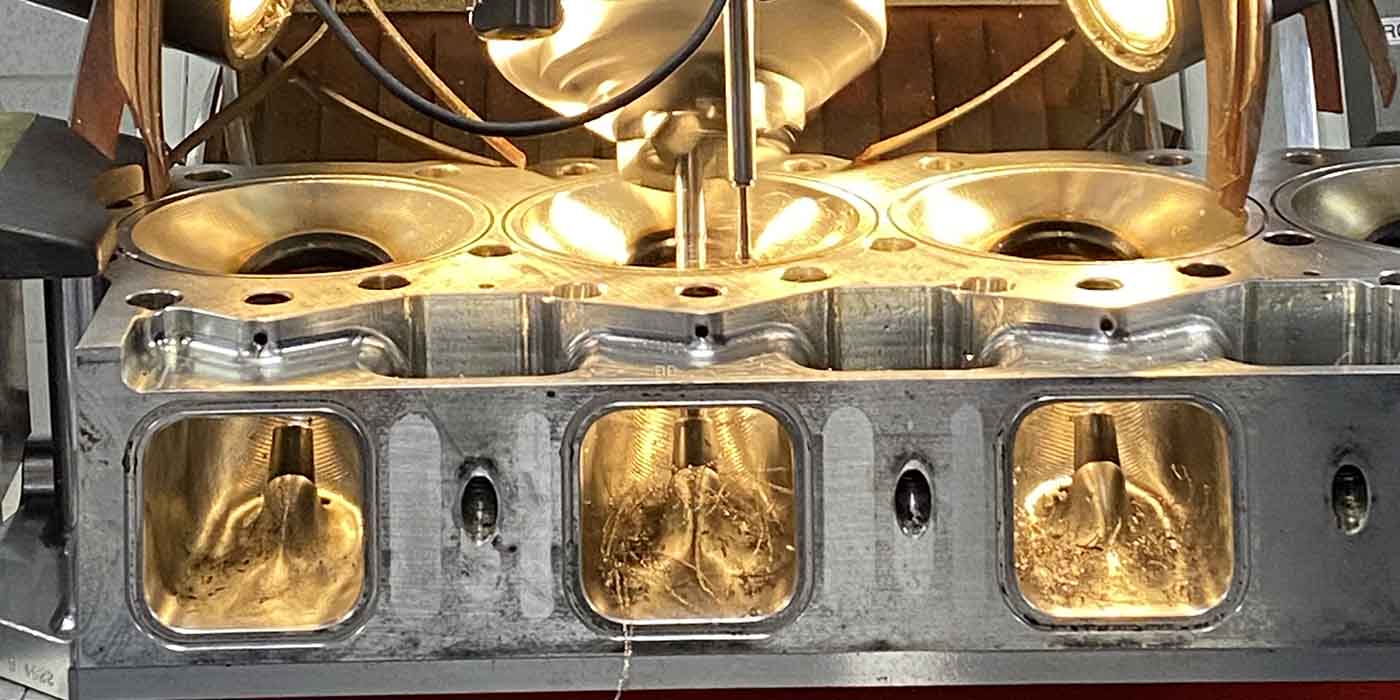
the cylinder head. If both a uniform seat width and leak-free seal
around the guide can be obtained, then the original concentricity was
not a problem. Also note that the exhaust valve guides are water-cooled and have two different-size press-fit diameters.
GUIDE REMOVAL
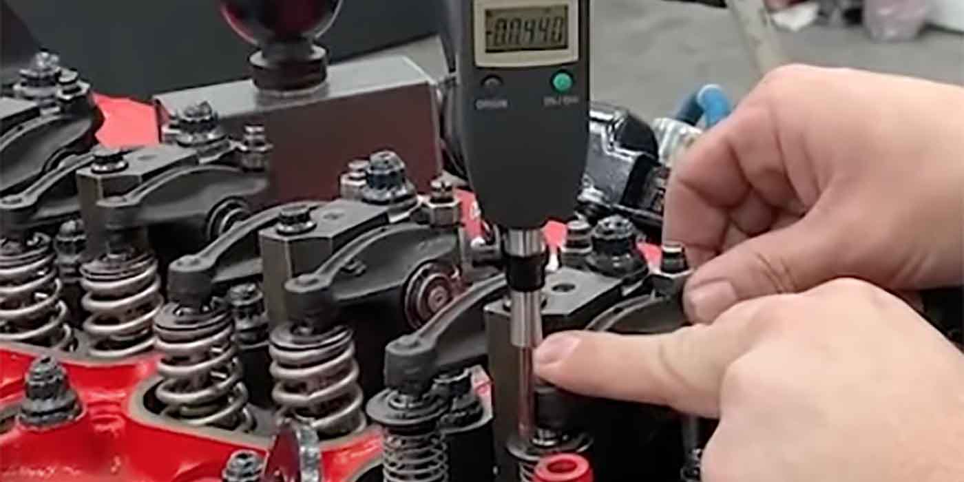
1. Measure and record the installed height above the cylinder head of the original valve guide.
2.
First of all, note that from year model 1985, GM has used a different
method of sealing the water passages. Unfortunately, there is no known
method to determine the size and type of guides in the cylinder head.
SBI recommends driving the guide toward the spring seat approximately 0.250? (6.35
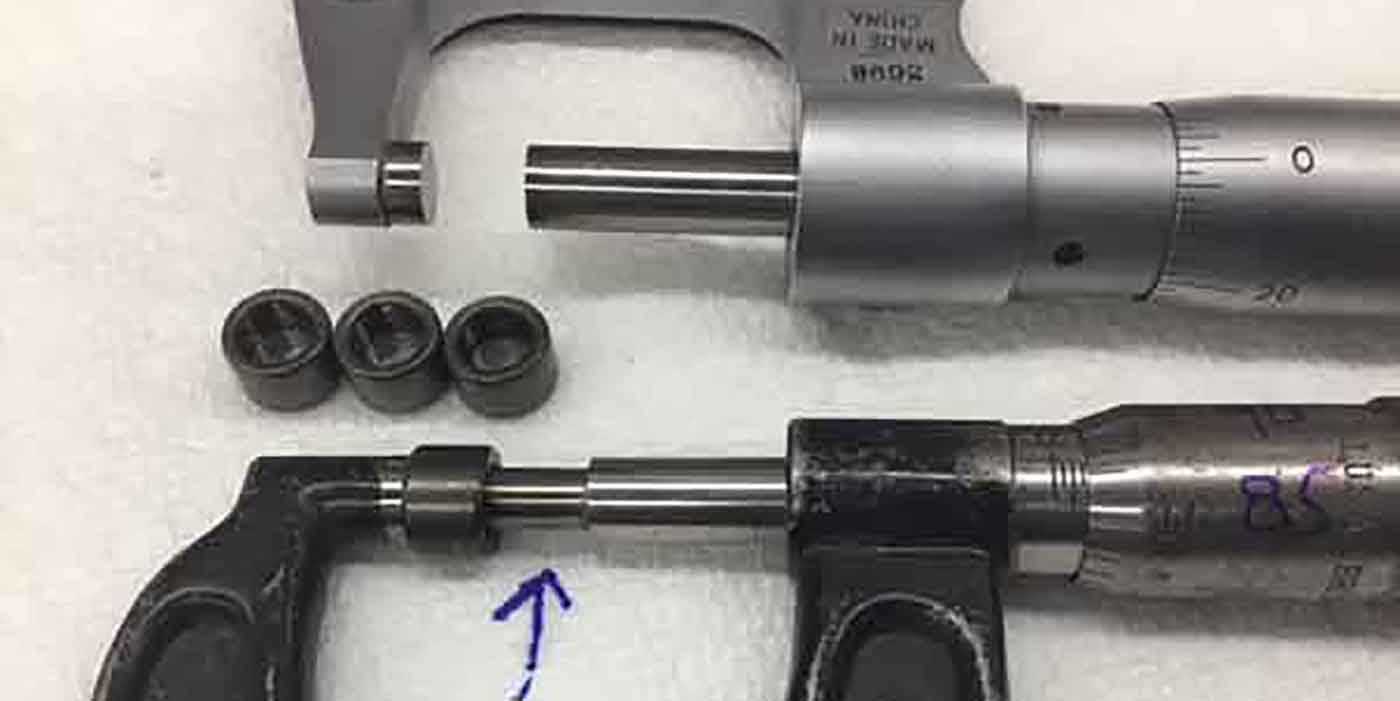
mm). Measure the guide’s outside diameter closest to the spring seat. If the guide’s
O.D. is .620? it is the old-style guide, which interchanges with SBI valve guide
number 140-1972. Drive the guide out from the combustion chamber towards the
spring seat.
If the guide measures .616?, it is the new-style guide. (Please refer to application
listing to guide part number.) To remove this new-style guide, perform the exact
opposite procedure mentioned above for removing the old-style guide: Drive the
guide out from the spring seat towards the combustion chamber.
CAUTION: If the valve guides are removed in the wrong
direction, the head may be damaged, which may result in water leakage
into the combustion chamber as well as offset seat-to-guide
concentricity.
GUIDE INSTALLATION
1. Make sure the correct guide is being installed when replacing a guide in the
different type cylinder heads. Aluminum cylinder head castings use the same
guide for both intake and exhaust valves, with the undercut on one end only. On
the other hand, cast iron cylinder heads have an exhaust guide that is undercut on
both ends and an intake guide that is undercut on one end only.
IMPORTANT: For valve guides that
are undercut on both ends, insert the end of the guide that measures
.616?/.617? in diameter toward the combustion chamber. If both ends
of the valve guide measure the same diameter, insert the end with the
lesser chamfer toward the combustion chamber.
2. Remove debris from guide hole. The guide hole must be clean for the new guide
to seal the water passage.
3. Insert the correct undercut end of the guide into the hole; make sure that the
correct end of the valve guide (as instructed above) points towards the
combustion chamber side of the cylinder head. The guide must be driven into the
cylinder head from the same side as removed: If the original guide was removed
from the spring seat side, the replacement guide must be installed from the spring
seat side; conversely, if the original guide was removed from the combustion
chamber side, the replacement guide must be installed from the combustion
chamber side.
4. Pressure test the cylinder head for leakage. If water from the water passage leaks
around the valve guide, repeat removal and installation steps before discarding the
cylinder head. Always remember that not all guides in these cast heads are
replaceable due to variations in the factory production methods.
– Tech Tip courtesy of S.B. International.


