This information is an update to previously published information on cylinder sleeve replacement for 2002-2006 GM Ecotec 2.0L, 2.2L and 2.4L 4-cylinder engines.
A Cylinder Sleeve Removal/Installation tool (p/n EN45680-850) is required for this procedure. Tools are available from Kent Moore.
Do not chill or heat the cylinder bore sleeve or the cylinder block when removing or installing a new cylinder bore sleeve. Chilling or heating the cylinder bore sleeve or cylinder block will cause damage and will not aid the removal or installation of the new cylinder bore sleeve.
Do not use assembly aids or lubricants on the cylinder bore sleeve or the cylinder bore block when installing a new cylinder bore sleeve, or engine damage will occur. These items will not aid in the installation of te new cylinder bore sleeve.
Also, don’t heat the clyinder bore sleeve or block when installing a new sleeve. Chilling or heating will cause engine damage and will not aid in the installation or removal process.
Place the new cylinder bore sleeve into the block.
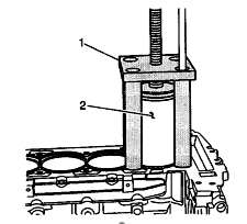
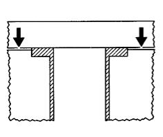
Install EN 45680-851 fixture and EN 45680-853 cylinder bore sleeve installer assembly over the cylinder bore sleeve and onto the cylinder block. Do not apply downward pressure to the cylinder bore sleeve.
Use the correct fastener in the correct location. Replacement fasteners must be the correct part number for the application. Fasteners requiring replacement or fasteners requiring the use of thread locking compound or sealant are identified in the service procedure. Do not use paints, lubricants or corrosion inhibitors on fasteners or fastener joint surfaces unless specified.
These coatings affect fastener torque and joint clamping force and may damage the fastener. Use the correct tightening sequence and specifications when installing fasteners in order to avoid damage to parts and systems.
Use four old cylinder head bolts for the attaching bolts.
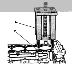
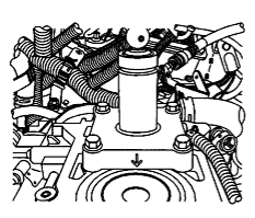
3) Insert the 4 attachment bolts into the legs of the EN 45680-851 fixture (1). Do not apply downward pressure to the cylinder bore sleeve (2). See Figure 1.
Tighten
Tighten the 4 attachment bolts to 11 ft.lbs. (15 Nm).
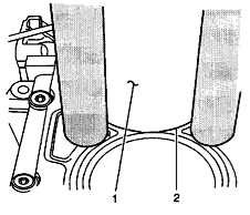
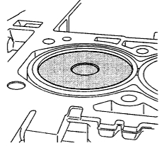
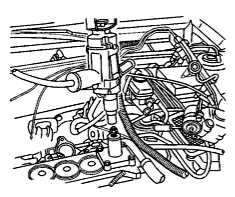
4) Align the bottom of the cylinder bore sleeve (1) with the cylinder bore of the block (2). See Figure 2.
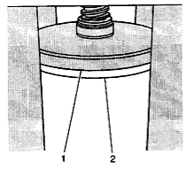
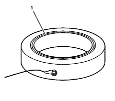
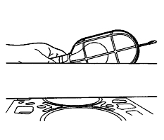
5) Align the installation arbor (1) onto the top of the cylinder bore sleeve (2). See Figure 3.
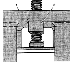
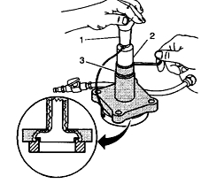
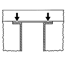
6) Align the pusher block (2) of EN 45680-853 cylinder bore sleeve installer into the groove of EN 45680-851 fixture (1). See Figure 4.
Do not use any air powered or electric tools to rotate the threaded shaft of the fixture EN 45680-851/cylinder bore liner installer EN 45680-853 assembly or damage to the cylinder bore liner will occur.
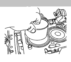
7) Using a ratchet, rotate the threaded shaft of EN 45680-851 fixture and EN 45680-853 cylinder bore sleeve installer assembly in order to install the sleeve into the block (see Figure 5).
8) Do not completely seat the sleeve in the block. Leave approximately 1/16? of the sleeve above the surface of the block.
9) Using a torque wrench, tighten the threaded shaft of the EN 45680-851 fixture and EN 45680-853 sleeve installer assembly to 75 ft.lbs. (102 Nm) in order to completely seat the sleeve into the engine block (see Figure 6). With the cylinder sleeve properly installed, a minimal portion of the liner flange will protrude above the block deck surface.
10) Remove the EN 45680-851 fixture and EN 45680-853 sleeve installer assembly (1) from the block (2). See Figure 7.
Cylinder Liner Trimming
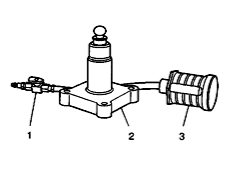
• EN 45680-865 Debris Collector (3). See Figure 8.
• EN 45680-861 Trim Tool Assembly (2).
• Air Control Valve (1).
• Drill Motor with 1/2? chuck, 1-1/8 hp, 7 amps, triple grear reduction, and 450-600 rpm rotational speed in clockwise direction.
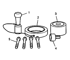
• Trim Tool Preloader (1). See Figure 9.
• EN 45680-862 Set Gage Ring (2)
• EN 45680-863 Metal Shavings Catch Plug (3)
• EN 45680-866 Drive Adaptor (4)
• EN 45680-864 Bolts (5)
Do not bore or hone the cylinder bore sleeve. The cylinder sleeve inside diameter (I.D.) is fully machined and honed to size and is optimally finished as shipped. Any attempt to modify this factory-produced sizing and finish with additional boring and honing will lead to engine damage, excessive noise or abnormal oil consumption.
1) After installing the new cylinder sleeve(s) into the engine block, trim the excess material from the cylinder bore sleeve flange (see Figure 10). Make sure all the metal particles are collected in order to prevent internal damage to the bearings.
2) Place the EN 45680-863 metal shaving catch plug into the cylinder sleeve to be trimmed (for in vehicle repair). Position the top of the EN 45680-863 approximately 3.0 mm (.120?) below the top surface fo the cylinder sleeve.
3) Place additional EN 45680-863 metal shaving catch plugs into all remaining cylinder sleeves. Installing the metal shaving catch plug EN 45680-863 deeper thant the recommended depth will create a decrease in vacuum system performance.
A decrease in vacuum will cause the metal shavings to enter the engine and cause engine failure. Installing the metal shaving catch plug above the recommended depth will cause damage to the catch plug. See Figure 11.
4) Be sure that the EN 45680-863 catch plug is 3 mm or .120? below the top surface of the cylinder sleeve.
Before using EN 45680-861 trim tool assembly, the height fo the cutting blades must be set to the proper specification.
The proper specification is that the cylinder sleeve flange must be flush to .02 mm or .0008? above the deck surface (See Figure 12).
5) The groove side of the EN 45680-862 set gage ring (1) should be positioned upward on a flat surface (see Figure 13). Ensure that the EN 45680-862 set gage ring surfaces are clean.
6) Carefully position EN 45680-861 trim tool assembly onto the EN 45680-862 set gage ring (2).
7) Loosen the shaft collar screw (2).
8) Push the shaft collar (2) downward using the trim tool preloader (1) until the shaft collar is positioned against the top of the flange bearing (3). Once this procedure is done, it is not necessary to reset the EN 45680-861 trim tool height until the blades are worn or damaged.
9) Apply downward pressure on the collar and inner drive shaft using the trim tool preloader (1), then tighten the shaft collar screw.
Tighten
Tighten the shaft collar screw to 14 ft.lbs. (19 Nm).
10) Place the EN 45680-861 trim tool assembly onto the cylinder to be trimmed with the directional arrow pointing in line with the crankshaft centerline and the front of the engine block. See Figure 14.
11) Install the four EN 45680-864 bolts into the cylinder head bolt holes in the block.
Tighten
Tighten the bolts to 15 ft.lbs. (20 Nm). For the proper tool operation, a drill motor with 1/2? chuck, 1-1/8 hp, 7 amps, triple grear reduction, and 450-600 rpm rotational speed in clockwise direction must be used. If the proper drill motor is not used, damage to the cylinder sleeve may occur.
12) Fasten the drive adaptor EN 45680-866 into the drill chuck (see Figure 15).
13) Connect a compressed air supply (75-125 psi) ot the male quick connect located on EN 45680-861 trim tool. Turn the compressed air valve to the open position. This starts the venturi vacuum system that will catch the metal shavings. Make sure that there are no crimps in the feed hose or vacuum hose. Crimps may cause metal shavings to exit the cutting tool in any direction.
14) Place the EN 45680-866 drive adaptor and the drill assembly vertically onto the EN 45680-861 end of the trim tool. Do not apply downward force on the drill until full rotational speed has been reached.
After reaching full rotational speed, gradually apply downward force until the cutting action is complete in approximately 5 seconds.
15) Remove the EN 45680-866 drive adaptor (1) and drill assembly from the EN 45680-861 trim tool assembly.
16) Turn off the compressed air valve.
17) Remove the EN 45680-861 trim tool assembly from the engine block.
18) Wipe the clylinder bore sleeve and the surrounding areas of any powder residue. Remove the EN 45680-863 metal shaving catch plug.
19) Install a straight edge on the cylinder block perpendicular to the crankshaft centerline (see Figure 16).
20) Using a light, illuminate the backside of the straight edge.
21) Looking at the front of the straight edge, inspect to see if light is protruding through the bottom of the straight edge and the top fo the cylinder sleeve flange. If light is present on either side of the sleeve, the sleeve is cut incorrectly and a new sleeve must be installed (see Figure 17).
22) Looking at the front of the straight edge, inspect to see if light is protruding through the bottom of the straight edge and the top of the engine block deck surface. If light is present on on both sides of the block, the sleeve is cut correctly (see Figure 18).
23) Proceed to the next bore sleeve to be trimmed, repeating steps 10-19 if necessary.
Some or all of this information was provided by the Automotive
Parts Remanufacturers Association (APRA). For more information on
technical bulletins available through APRA call 703-968-2772 or visit www.AutoBulletins.com.