The two methods of adjustment are internal (dry) setting and the external (wet) setting. The internal float adjustment is accomplished with the fuel bowl off the carburetor.
 With “internally adjustable” needle and seats, the fuel bowl is inverted and the float tang, or tab, is adjusted to the point where the float surface is parallel to the fuel bowl surface, just underneath. An initial dry setting can also be accomplished with “externally adjustable” needle and seats. To achieve this, invert the fuel bowl and turn the adjusting nut until the float surface lies parallel to the fuel bowl casting surface underneath.
Another, more accurate adjustment can be made with the side hung style float if measuring gauges, such as drill bits, are available. Here, with the fuel bowl inverted, the primary float can be adjusted to the point where there is a 7/64? gap between the “toe” of the float and the bottom of the fuel bowl surface underneath. The float “toe” is the part of the float furthest from where the arm is attached. The secondary float can be adjusted to the point where there is a 13/64? gap between the “heel” of the float and the bottom of the fuel bowl surface underneath. The float “heel” is the part of the float closest to the point where the arm is attached.
A “wet” level float adjustment can be performed on either the side or center hung floats, if the fuel bowls have provision for the externally adjustable needle and seats. This adjustment is made as follows. Start the engine up and allow the idle to stabilize. Turn the engine off and remove the sight plug from the primary fuel bowl to inspect the fuel level.
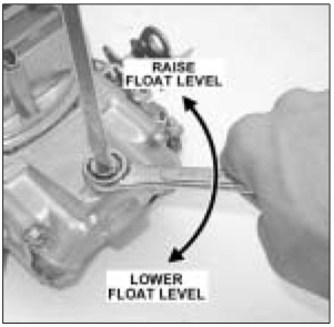
If it’s been determined that adjustment is required use a large screwdriver to crack loose the lock screw. With a 5/8? open-end wrench turn the adjusting nut clockwise to lower the float level.
Conversely, turn the adjusting nut counter-clockwise to raise the float level. Tighten the lock screw. Restart the engine and let the idle stabilize. Shut the engine off. Remove the sight plug to reinspect the fuel level. The fuel level should stabilize at just below the level of the fuel bowl sight plug hole. This same adjustment procedure is performed on the secondary bowl.
Note: The float adjustment cannot cure a poor running engine, a bad ignition system, a clogged fuel filter, an improperly operating fuel pump or fuel pressure that is too high or low. This adjustment is provided solely to ensure that the fuel in the bowl can be adjusted to the correct level for the carburetor to perform its function.
Source: Holley


