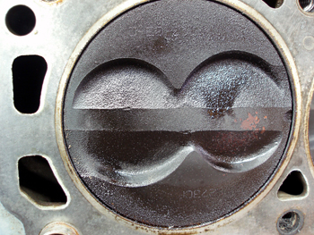
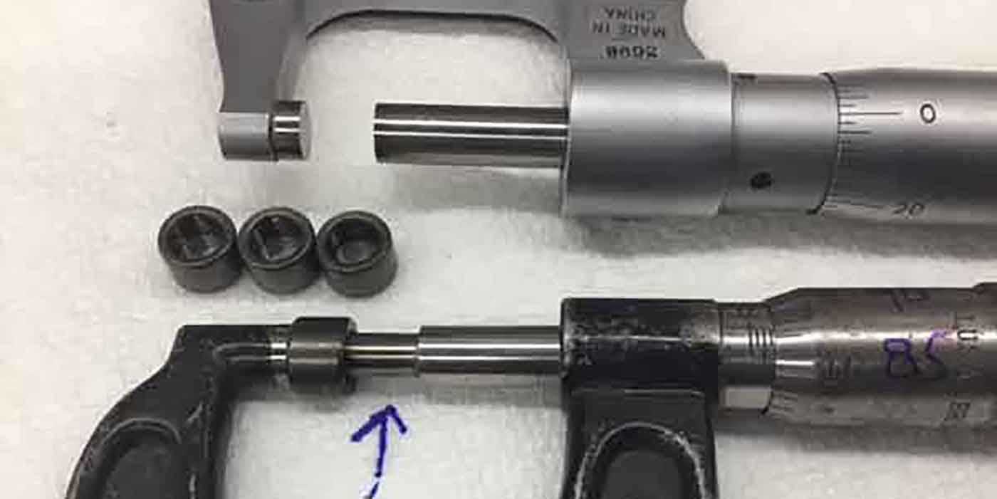
Under my supervision, we removed the oil pan with the engine in an upright position to keep all metallic debris at the bottom of the oil pan. With the exception of two very small metallic particles, the oil pan was surprisingly clean. But when we turned the crankshaft, we discovered that #1 and #4 pistons were once again scored.
In-Depth Analysis
In accordance with Murphy’s Law, the probability of two different sets of pistons scoring on the same cylinders is nearly zero. Measuring piston skirt-to-cylinder wall clearances with a set of long feeler gauges, I found that six cylinders had 0.002” oil clearance. But #1 cylinder was worn to 0.010” clearance and #4 was worn to 0.012” clearance, all within 700 miles of operation..
As expected, the rebuilder insisted that an external factor in the ignition or fuel system was causing #1 and #5 pistons to overheat and score. But all of the fuel injectors subsequently passed a pressure-drop and flow pattern test. The spark plug colors appeared normal and further diagnosis didn’t indicate a situation that could cause both end cylinders to run lean.
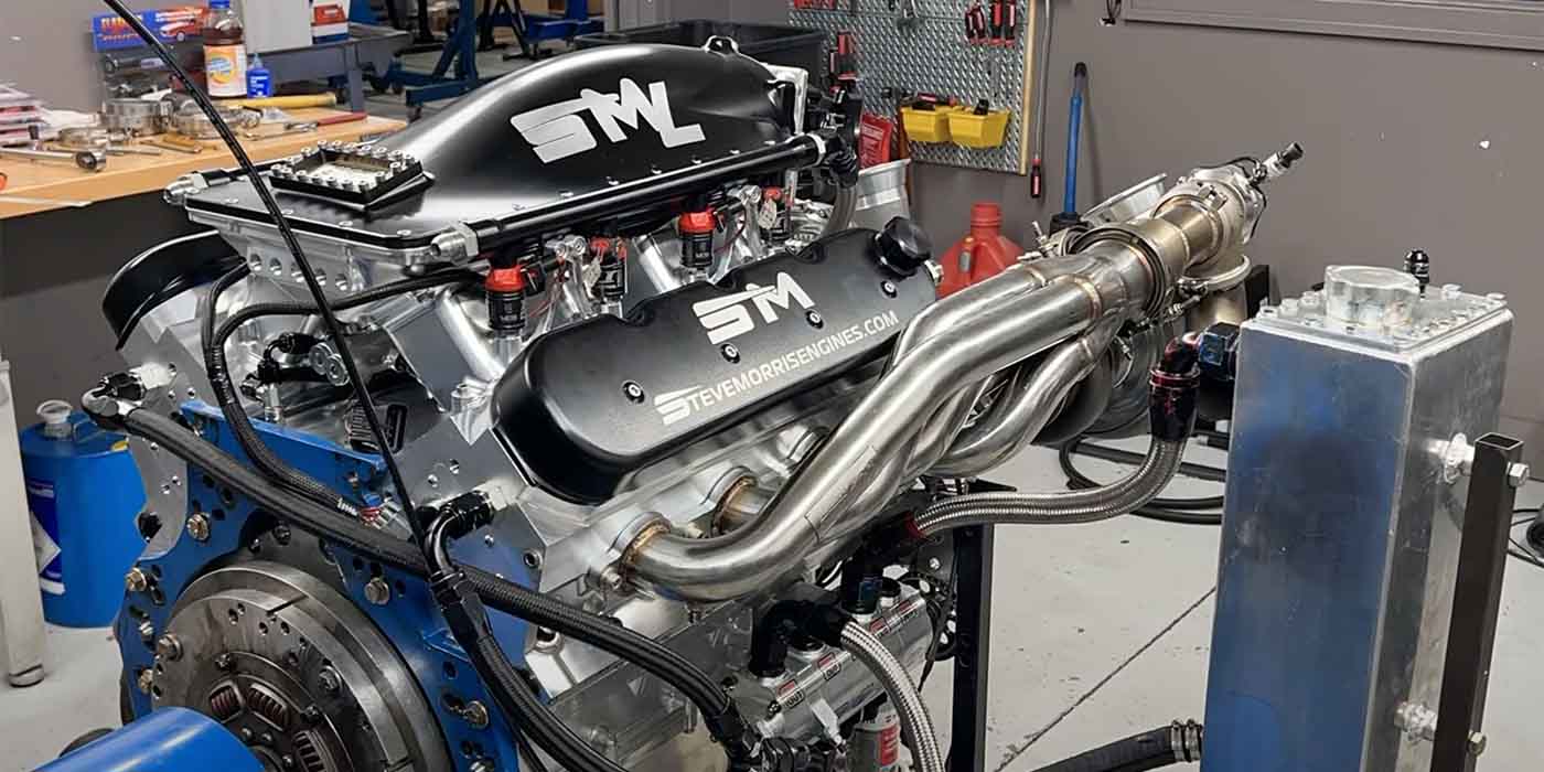
See Photo 4.
At this point, I’ll mention that some 5.0L Ford engines had preignition problems caused by #7 and #8 spark plug wires being routed parallel to the other. In some cases, spark induction from one wire to the other can burn a hole through the piston on one of these cylinders. Of course, that wasn’t the case here, but it’s worth mentioning just for the record.
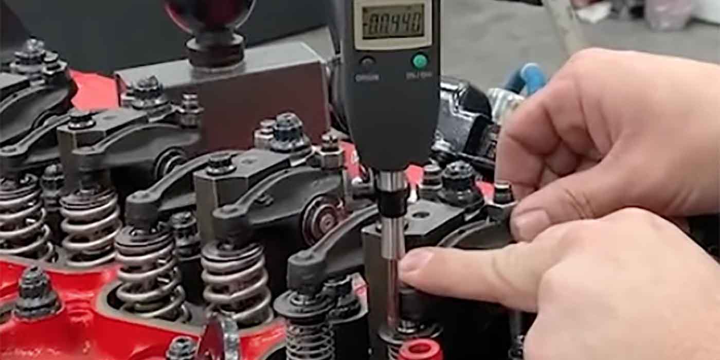
Piston Analysis Like all diagnostic techs, I don’t like to be defeated on any diagnosis. Once I had the right-bank piston and connecting rods in hand, I began measuring the pistons. I noticed that the wrist pin offset was about 0.100” or nearly an eighth of an inch.
While most pistons incorporate some pin offset to reduce piston slap during cold engine operation, I thought that 0.100” was more than usual.
Next, I placed a good piston in my deep freeze so I could measure the cold diameter of the piston. I was surprised that the piston diameter shrank 0.017” at 0° F. At this temperature, the wrist pins also began to stiffen. But, when heated to 200+° F, the skirt diameter barely increased by 0.002”, which (considering the cylinder diameter expands as well) was within the 0.002” skirt-to-wall clearance machined into the cylinders. In addition, the wrist pins moved freely when the piston dome was heated to 400+° F.
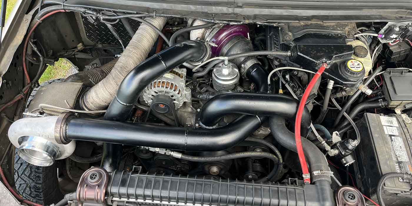
See Photo 5.
[inpost_gallery post_id=4910 group=”2″]
I would have needed the services of an independent engineering lab if the matter went to litigation. But that wasn’t the case, so, based on my experience and observations, I felt that the root problem was caused by faulty metallurgy in the piston. But why did cylinders #1 and #4 fail in two consecutive rebuilds? If the metallurgy was at fault, why didn’t other cylinders fail?
Basic Piston Construction
The aluminum used in modern pistons contains about 5% silicon content to harden the aluminum and make it compatible with cast-iron cylinder walls. The piston is ground slightly egg-shaped and the piston head itself is generally about 0.010” less in diameter than the skirt to allow for heat expansion.
Many conventional aluminum pistons also use steel struts molded in place around the wrist pins to control piston expansion as the engine warms up.
On the other hand, many modern engines are equipped with hypereutectic pistons, which have about 15+% silicon content.
The characteristics of hypereutectic piston are:
1) combustion heat travels very slowly through the metal. Consequently, less heat energy is dissipated to the oiling and cooling systems.
2) Because the piston dome runs hotter, piston ring end gaps must be increased.
3) The skirt-to-wall clearances can be reduced because the pistons’ skirts themselves run much cooler.
4) Tight skirt-to-wall clearances promote better ring sealing by holding the piston rings squarely against the cylinder wall.
The pistons in my hand were typical “rebuilder’s pistons” made in Asia. With the exception of domestic performance manufacturers, most rebuilder’s pistons are, in fact, manufactured in Asia. These pistons had no steel inserts and were presumably hypereutectic pistons. The pistons were also coated with an anti-scuffing agent. The rebuilder said that he had used these pistons many times with no negative results.
Lubrication Theory
As mentioned above, the half-speed piston tapping noise occurred during the first warm-up on the new engine. Due to the 0.100” wrist pin offset, a major load is placed on the thrust skirt to prevent cold engine piston slap. With these facts in mind, I analyzed the 5.0L lubrication system.
As with most engines, the upper main bearing shell is grooved to allow oil to flow from the main bearing to the connecting rod bearing for one-half revolution of the crankshaft. Due to the V8 configuration, the piston skirts aren’t being oiled from the connecting rod oil as the piston approaches top dead center.
The piston skirts are instead oiled by “windage” that develops in the engine as the oil turns into a fine oil mist that circulates around the interior of the crankcase in the direction of crankshaft rotation.
Looking from the front of the engine, it’s easy to see that most of the oil windage directed at #1 and #4 pistons ends up in the oil pan, especially during cold engine operation. Number 5 and #8 cylinders on bank two receive the full force of oil windage whereas cylinders #1 and #4 don’t.
The center four cylinders apparently receive plenty of windage lubrication, cold or hot. In theory, if the metallurgy or construction of the rebuilder’s pistons were defective, then it would be #1 and #4 that would fail first. Keep in mind that this is just speculation on my part.
Engine Number Three
In the short version of engine number three, we specified that the replacement pistons were to be supplied by a well-known domestic manufacturer of hypereutectic pistons. The installer also insisted on starting with another cylinder block assembly to eliminate the possibility of bad connecting rods or crankshaft oiling issues. The owner also insisted on installing a reground crankshaft kit to eliminate possible oiling issues.
The engine was installed and ran perfectly for 30 miles until it lost oil pressure. When cut apart, the oil filter was full of copper metal sheared from the main bearings.
Upon disassembly, I discovered that the main bearings had developed over 0.012” of clearance. Since the maximum spec is 0.003,” it’s easy to see why the engine lost oil pressure. Other than some slight scuffing due to lack of oil pressure, the connecting rod and camshaft bearings were perfect.
Using a 30x-power magnifier, I discovered that the main bearing journals were coated with microscopic bits of copper. Despite the condition of the main bearing inserts, the crankshaft journals were dimensionally perfect.
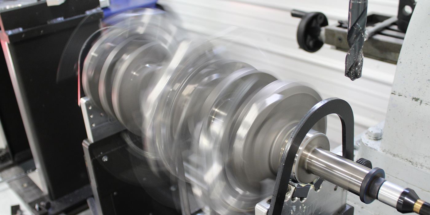
Thanks to a TSB made available by an engine machinist who regularly posts on iATN, I discovered that a crankshaft reground and polished in the wrong sequence and rotation can ruin a new set of bearings. The TSB, which was published by a major engine bearing manufacturer, indicates that crankshafts must be ground opposite of engine rotation and polished in the direction of engine rotation.
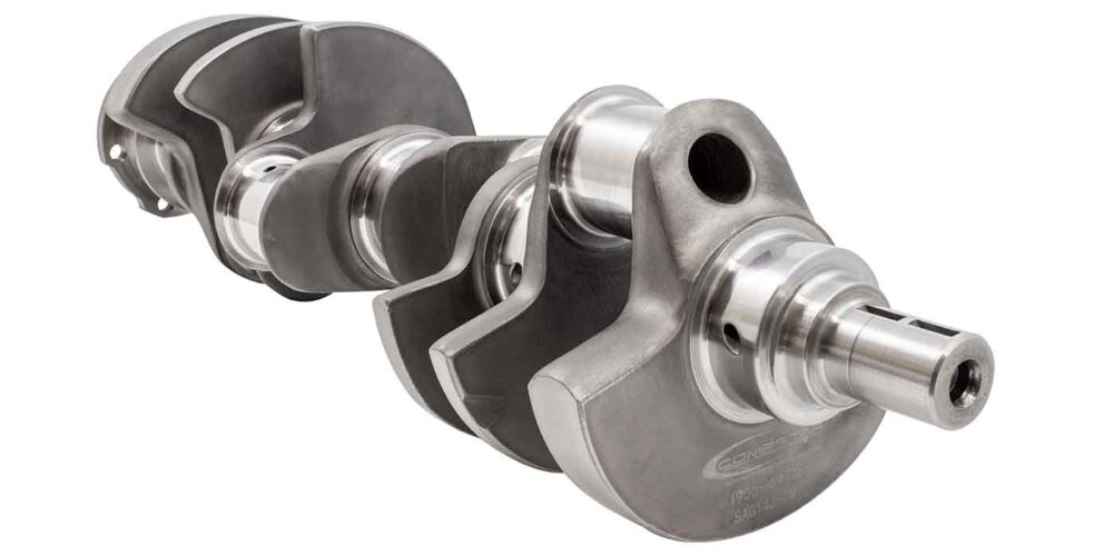
Nodular cast iron, which is used in some 5.0L crankshafts, is particularly sensitive to regrinding and polishing techniques. Reversing this procedure raises a “micro-fuzz” on the journal surfaces that rapidly files away soft bearing material. If a high-speed crankshaft polisher is used, rotational direction is not an issue.
Last, but not least, I discovered that custom crankshaft grinders generally use the same machine for grinding and polishing. Production facilities, on the other hand, generally grind the rod journals on one machine and pass the crankshaft onto another machine to grind the main journals. The latter statement explains why the connecting rod bearings survived while the main bearings were severely worn.
Summary
While it’s simply an educated guess on my part, I believe that the pistons’ metallurgy, the relatively large wrist pin offset, and the relative lack of start-up lubrication on those cylinders combined to cause the subsequent piston failures on the #1 and #4 cylinders. The crankshaft failure was simply the application of bad parts and Murphy’s Law.
Whatever the case, I helped assemble a fourth engine using the new performance pistons from the third engine and the crankshaft from the second engine. So far, the fourth engine has done well. The financial impact of these events was devastating to all involved. I donated much of my time getting to the bottom of each problem. The final cost is incalculable to the installer, rebuilder and end user.
On a more global scale, this article is an extreme illustration of how our cost of doing business is impacted by the distribution of substandard replacement parts. Keep in mind that there is a vast difference between the price of buying a part and the cost of using a part.
The price is known whereas the cost is always an unknown. Given sufficient volume, the cost of using faulty parts can devastate the economic welfare of distributor, installer and end user alike.

