Pushrod engines new and old are still a hot topic.
Overhead cams have been used in many European and Asian engines for years, so when Ford opted to go the overhead cam route with their 4.6L V8 engine, some predicted pushrod engines were on their way out. But, GM stuck with the pushrod design for their LS engines as did Chrysler with their 5.7L & 6.2L Hemi engines.
When you add in all the older engines and current aftermarket block/head combinations that still use pushrods and rocker arms, it’s easy to understand why rocker arms and pushrods are still a hot topic for performance engine building.
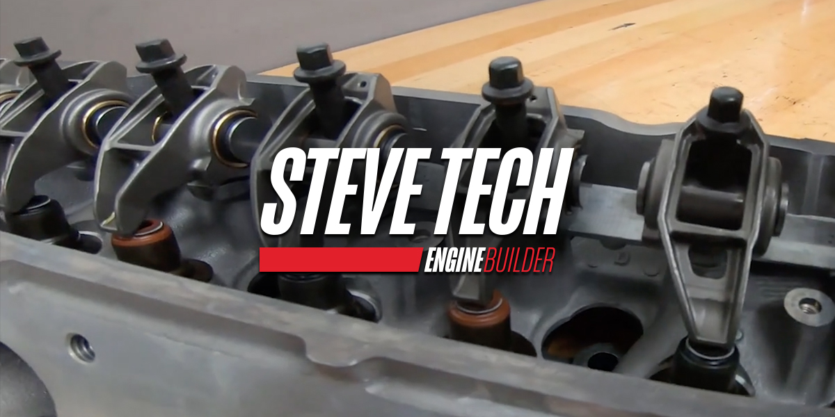
The rocker arms redirect the upward motion of the lifters and pushrods into the downward motion required to open the valves. The rocker shaft or ball stud mounting serves as the fulcrum point around which this motion occurs, and the relative length of the rocker arm on each side of the center fulcrum determines the lift ratio of the rocker.
Like any lever, leverage is multiplied when the valve side of the rocker arm is longer than the pushrod side. The shorter the pushrod side of the rocker arm and the longer the valve side of the rocker arm, the higher the lift ratio of the rocker.
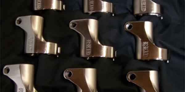
Click on an image to view gallery
[inpost_gallery post_id=3578 group=”1″]
If the length of the valve side of the rocker is 1.5 times that of the pushrod side, the lift ratio will be 1.5:1. If the valve side of the rocker is 2X the length of the pushrod side, the lift ratio will be 2.0:1.
If you’re using a typical street performance cam in a smallblock Chevy V8 that produces .480˝ of total lift at the valve, the cam itself is only producing about .320˝ of lift at the lobe. The 1.5 ratio rocker arms multiply the lift (.320 x 1.5) to achieve the .480˝ of lift at the valve.
The advantage of using higher ratio rocker arms is that the same cam lobe profile can produce more total valve lift for more power.
A higher ratio rocker arm also requires less lifter and pushrod travel to achieve the same amount of lift as a lower ratio rocker. A higher rocker ratio also reduces the amount of camshaft torque it takes to open the valves for a given amount of lift. What’s more, the longer the valve side of the rocker, the larger the diameter of the arc it follows as it moves up and down. This reduces side loading, friction and wear on the valve stems and guides. This is why many high revving NASCAR engines typically run very high rocker ratios of up to 2:1 or higher.
Changing Rocker Ratios
Let’s say to replace the stock 1.5 ratio rocker arms with higher lift 1.6 ratio rocker arms. The same camshaft will now produce .512˝ of lift at the valve (.320˝ times 1.6). So by simply swapping the stock rocker arms for higher lift rocker arms, you increase total lift 6.7% and probably gain 15 to 20 horsepower.
How does changing rocker ratios affect the duration of the camshaft? Because the cam lobe is still the same, the point where the cam starts to move the lifter is still the same. Ditto for the closing side of the ramp. But, the rate at which the valve opens is now somewhat faster because of the higher ratio of the rocker arm, so the effective duration of the camshaft is increased slightly – maybe a couple of degrees in the above example.
A small ratio change won’t have a big impact on the rpm range where the engine makes power, or its low end torque, idle quality or the amount of intake vacuum it produces. But, a large change in lift ratio that increases mid-range duration significantly will move the engine’s power peak up the rpm scale. That’s why wild cams with lots of duration and valve overlap that produce tons of high speed horse power are typically bad for low end torque, idle quality and everyday drivability.
There are a couple of things you have to watch out for when changing rocker ratios. One is to make sure the slot in a stud mounted rocker can accommodate the increased travel without hitting the stud. Something will break if it does. Another is to make sure the valve keeper doesn’t hit the top of the valve guide when lift is increased. There has to be some clearance to prevent mechanical contact. Also, the valve springs have to have enough clearance between the coils so the springs don’t bind – which would be another valvetrain killer.
Stud Mount vs. Shaft Mount Rockers
Up until the mid-1950s, overhead valve engines used shaft mounted rockers. When Chevrolet introduced their high revving small block V8s with stamped steel stud mounted rockers, it opened the eyes of engine designers to the possibilities of stud mounted rockers. Ford and others soon followed suit, and stud mounted rockers became the “hot” setup for the time.
As engine builders made modifications to increase engine speed and power, the stud mounted rockers started to show their weaknesses. The press-fit rocker studs had a tendency to pull out if the engine was revved excessively or spring pressures were increased too much. Some performance engine builders started pinning the studs to keep them in place, while others replaced with press-fit studs with screw-in studs.
As valve spring pressured continued to increase, it became obvious that the rocker arm studs were flexing excessively at high rpms. The fix was to install longer studs and to clamp a bar (stud girdle) across the top of the cylinder head to tie all the studs together.
This, in turn, required taller valve covers to accommodate the stud girdle. It also made valve adjustments more difficult.
Aftermarket roller rocker arms were also introduced to replace the flimsy and rather wear stamped steel stock rockers. The performance rockers featured a roller bearing center fulcrum and a roller on the valve end of the arm to reduce friction. These were a huge improvement over the stock rockers and allowed higher rpms with more dependability and less friction.
As racers continued to push the envelope, it soon became apparent that some of these stud mounted aluminum rocker arms were not strong enough to handle the valve spring loads and rpms they were being asked to handle.
Aftermarket shaft-mounted rockers were introduced as a means of stiffening up the valvetrain, and steel rockers became an upgrade option for serious high-dollar racing.
According to some manufacturers, changing from stud mounted rockers to shaft mounted rockers (using the same lift ratio as before) will typically produce 10 to 15 more horsepower thanks to increased valvetrain stability.
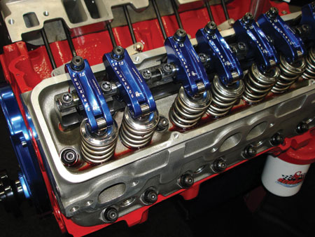
The advantages of a shaft rocker setup is that the shaft holds the rockers in better alignment, eliminating the need for a separate guide plate for the pushrods. This reduces flex in the valvetrain at higher speeds for better valve control. The shaft can also supply oil pressure directly to the rockers to improve lubrication and reduce friction. The position of the shaft may also lower the pivot point of the rockers slightly with respect to the valves and pushrods to reduce friction between the tips of the arms and top of the valves.
A shaft mounted rocker arm system is overkill for most street performance applications because such an engine doesn’t really need that level of stiffness and strength. But for racing, a shaft mounted system can provide increased rigidity and reliability.
Supporting the rockers on a rigid steel or aluminum shaft means the rockers can’t deviate from their fixed location due to stud flex or vertical motion on the rocker stud. The stiffness provided by the shaft holds all the rockers in perfect alignment and allows them to safely handle higher loads and rpms. Shaft-mounted rockers also don’t require a slot cutout on the underside of the rocker body to clear a stud, so shaft rockers are inherently stronger.
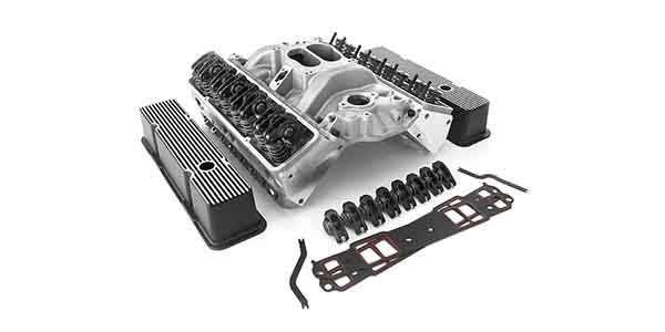
Shaft-mounted rocker systems are available for many aftermarket performance cylinder heads. In many instances, it’s a simple bolt-on installation that requires little or no modifications to the head. Pedestal mount rockers are also available for many engines with stud-mounted rockers.
A pedestal mount system can provide many of the same benefits as a shaft-mounted rocker system but at less cost. Many of these are simple bolt-in installations, but don’t expect them to perform at the same level as a true shaft-mount system in an all-out racing application.
A shaft-mounted rocker system also makes valve lash adjustments easier than stud-mounted rockers with a stud girdle, and the lash adjustments should hold longer, too.
Choosing Rocker Arms
Today, engine builders have a huge variety of performance rocker arms and rocker systems from which to choose. There are the “economy” aluminum rockers typically made from diecast aluminum that provide an upgrade in performance over stock stamped steel rockers. But for more demanding applications, upgrading to CNC extruded or forged aluminum rockers or steel rockers is often necessary.
Light rockers are a must because they reduce mass in the valvetrain. Reducing the “moment of inertia” with lighter rocker arms allows the engine to rev higher with the same springs.
Rocker arms obviously have to be strong to handle the loads that are placed upon them, but reducing the mass on the valve side of the rocker arm has more of a positive effect on reducing inertia than changing the mass on the pushrod side of the rocker arm. This also explains why larger or stiffer pushrods that weigh more than stock pushrods have minimal effect on valvetrain momentum. You want stiffer and stronger pushrods for reliability and valvetrain stability, especially with higher valve spring pressures in a highly modified high revving engine.
Some of today’s steel rockers are just as light if not slightly lighter than a comparable performance aluminum rocker. Steel can safely handle a lot of valve spring pressure, up to 950 pounds or higher say the people who make such rockers. Steel has better fatigue strength and stiffness than aluminum, and will stand up to the rigors of racing for a longer period of time – often 2X to 4X as long as comparable aluminum rockers.
By comparison, the typical economy diecast aluminum rockers should not be used with more than 350 to 450 pounds of open spring pressure depending on the brand of rocker. Extruded aluminum rockers can usually handle up to 700 pounds of open spring pressure, with some rated for as much as 900 pound springs. Always go by what the rocker arm manufacturer says their arms can safely handle. Don’t push the rockers beyond their rated capacity unless you want to break something.
Something else to pay close attention to when choosing rockers is the design of the rollers and needle bearings. More needle bearings in the center bearing is better because it spreads the load over a larger surface for improved durability. The rollers on the tips of many rocker arms do not have needle bearings, but some do – which helps reduce friction and valve stem wear.
The type of rocker arms that are permitted may be restricted by the rules in some racing applications. If the rules call for “stock appearing” rocker arms or stamped steel rockers, that doesn’t mean you’re stuck using the stock rockers. Many aftermarket companies offer stock appearing stamped steel rockers that are made of stronger alloys for improved reliability.
And even if rules are not a limiting factor, stamped steel rockers can usually handle engine speeds up to 6,500 rpm and valve lifts of up to .600˝ as long as the rocker slot has sufficient stud clearance to handle a high lift cam. The same goes for cast steel rockers on Ford and Chrysler engines that use some type of shaft mounted rocker setup.
For engine applications that demand a step up, replacing the stock stamped or cast steel rockers with aluminum roller rockers will typically produce a gain of 10 to 15 hp with the same lift ratio, and even more of a power gain with a higher lift ratio. The extra power comes from the reduction in friction provided by the roller rockers – which also helps keep the oil cooler, too.
Installation Issues
Changing rocker arms often requires changing pushrod lengths, depending on the design of the rockers. With stud mounted rockers, the rocker arm location on the stud determines the geometry of the
valvetrain.
When the pushrod is the correct length for the application, the tip of the rocker arm will be centered on the tip of the valve stem when the cam is at 50 percent lift. If the pushrod is too long or too short, the tip of the rocker will be offset towards the outside or inside of the valve stem rather than centered over it. This can create side loads on the valve stem that increases friction, stem and guide wear.
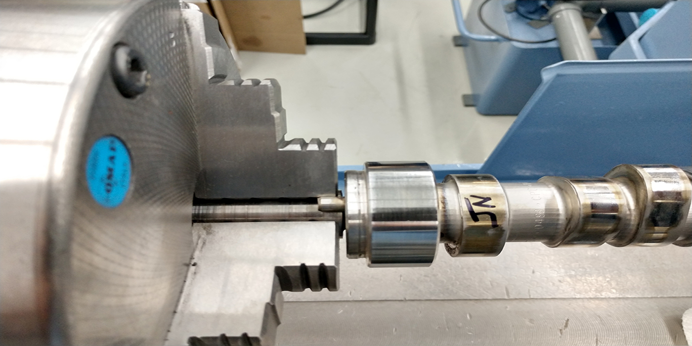
An adjustable length pushrod can be used to determine the optimum pushrod length for any rocker arm/camshaft combination.
Adjust the pushrod when the cam is at 50 percent lift so the tip of the rocker is perfectly centered, then remove the rocker and pushrod, and measure the end-to-end length of the pushrod to determine the optimum pushrod length.
If the engine has hydraulic lifters, the lifter will collapse slightly when the valvetrain is under load. Using a light checking spring rather than an actual valve spring will allow a more accurate reading of the pushrod length.
Once the pushrod length has been determined, look for the stiffest and strongest pushrods that will fit the application and anticipated rpm range of the engine. Stock pushrods may be fine for stock valve springs and 5,500 rpm, but they’ll bend and flex with higher spring loads and rpms.