
By Dr. Dmitri Kopeliovich, Director of Research & Development, King Engine Bearings
As performance engine builders know, the loads acting on engine bearings are generated by the pressure of the fuel-air mixture combusting in the cylinders.
This pressure, or combustion force, drives the piston down during the engine power stroke.
However, combustion force is not the only force generated by an internal combustion engine.
Such engines contain parts performing accelerating/decelerating motion (either linear or rotating): pistons, connecting rods, crankpins, counterweights and webs of the crankshaft.
These parts generate inertia forces that are added to the combustion forces and therefore affect the support reactions of the bearings.
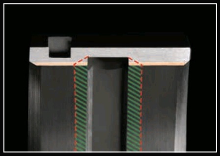
In our last installment in this series on performance engine bearing technology, King Racing Bearings looked at overlay thickness as it pertains to performance applications. In this tech installment, we’ll look at the effect of bearing geometry on load capacity and performance, in particular, King’s U-groove oil groove design (see illustration below).
Effect of the Oil Groove on Bearing Function
The inertia force generated by a rotating part of the crankshaft is directed from the rotation center to the center of mass. Therefore, it is transmitted to both the upper and lower main bearing shells. The oil groove is commonly made in the upper shell where the oil hole is located.
A 180º groove is sufficient for providing the required amount of oil to the connecting rod bearing, which it reaches by flowing through passageways within the crankshaft.
The lower main shell has no groove. Therefore, its effective area is greater than that of the upper grooved bearing.
This design allows distributing the load applied to the lower shell over a greater area, reducing the specific load acting on the bearing material. Since the lower bearing shell is generally loaded heavier than the upper, the specific loads of the two are balanced.
However, at high rotation speeds in high performance engines, the absolute loads applied to the upper and lower bearings may become close to each other. In this case the specific load (force per unit area) applied to the upper bearing may exceed the specific load to the lower bearing.
Loading Issues
Excessive loading of the upper bearing may cause the following two problems:
• Fatigue of the bearing material. Internal combustion engines are characterized by cycling loading of the bearings. It is caused by alternating pressure of combustion gases in the cylinders and inertia forces developed by accelerating parts. The oscillating loads applied to a part may cause bearing failure as a result of material fatigue. This occurs if the load exceeds the fatigue strength (load capacity) – the maximum value of cycling stress that a bearing can withstand after an infinite number of cycles.
• Too low minimum oil film thickness. High loads applied to the bearings result in a reduction of minimum oil film thickness. This may cause non-uniform distribution of the bearing load (localized pressure peaks) characterized by metal-to-metal contact between the bearing and shaft (mixed or boundary lubrication regime), high coefficient of friction (power loss), increased wear, and the possibility of seizure between the bearing and shaft materials.
New Design of Oil Groove (U-Groove™)
King Racing addressed these two issues, which lead to the development of a “U-groove” design. King engineers said the level of specific load applied to the grooved bearing may be lowered by means of a reduction in groove width. Figure 1 shows a cross section of a bearing with a conventional oil groove design. 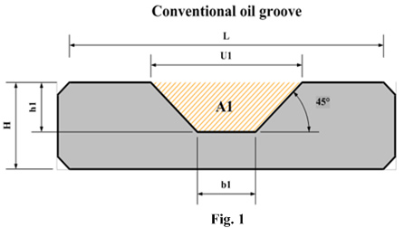 The effective bearing length is L-U1. It may be increased by a simple decrease of U1, but it would reduce the cross sectional area of the groove. This is an extremely undesirable modification, particularly for high performance bearings generating high oil flow rates due to operation at high rotation speeds. The connecting rod bearing is lubricated by oil passing through the main bearing groove and then the oil passages in the crankshaft. The amount of oil entering the connecting rod bearing should be not lower than the oil flow produced by the hydrodynamic lubrication of the main bearing. A reduction of the cross sectional area decreases the passage capability of the groove, which may cause a formation of oil starvation conditions in the connecting rod bearing. A new design should result in a reduction of the groove width without decreasing the groove cross sectional area.
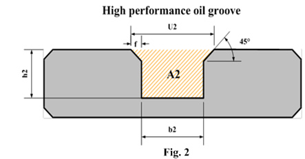
  The modification according to these demands is presented in Figure 2. The rectangular shape with small chamfers has allowed reduction of the groove width at the top (U) by at least 30%. On the other hand the cross sectional area “A” has not changed due to an increase of both groove width band groove depth “h.”
The modified groove for high performance bearings enables bearing operation with a thicker oil film. In spite of the fact that the difference is not as large as in peak oil film pressure, it may become crucial under conditions characteristic for high performance engines: high loads, low viscosity oils and high rotation speeds. For more information, check out the following video from King Racing.
Source: King Engine Bearing Specialists


