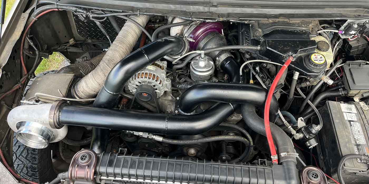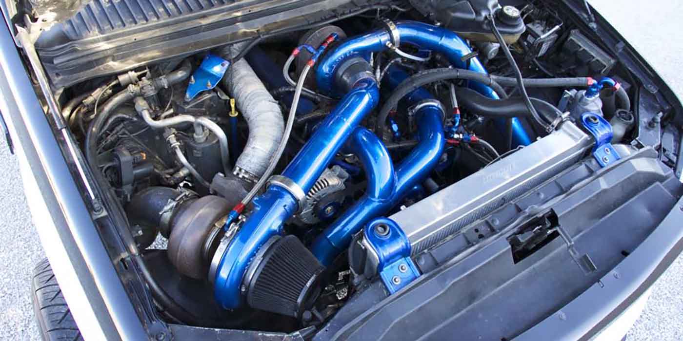
 The 6.0L Power Stroke (on right) has had a terrible reputation since its birth in 2003. I am sure that if you follow the diesel community, you will know that the 6.0L engines have suffered from quite a few plagues that have troubled them since their existence. The extent of the repairs become overwhelming and owners tend to cut their losses and send them on down the road.
On the top of the list of repairs would be the head gaskets and EGR coolers followed by stuck veins in the turbochargers, sticking injectors, high pressure oiling system leaks, faulty high pressure oil pumps, FICM (Fuel Injection Control Module) failure, oil coolers, and various sensors and actuators.
Because of these enormous failures, which can be quite costly, the 6.0L never lived up to the reputation of its forefather the 7.3L Power Stroke. The biggest question that I hear from customers is, “Why did Ford replace the 7.3L with the 6.0L?” There are good reasons as to why the 7.3L Power Stroke had to be removed from service and these reasons brought about many changes in the Power Stroke platform.
In order to appreciate the Power Stroke, think about what was taking place in the early 1990s with the “Big Three’s” diesel programs. You have to remember, the Cummins in the Dodge truck was taking the market share in diesel power,
so Ford needed something that was going to be able to compete with Dodge. GM’s division, Detroit Diesel, also had been offering a diesel engine for the Chevrolet truck, which had been in existence since 1982, known as the 6.2L, which ran in production until 1993. GM never did introduce the 6.2L as a powerhouse, but more for fuel efficiency. Trust me; this engine was no threat to the performance market.
To keep up with the Cummins, in 1993 GM produced another engine known as the 6.5L, which was turbocharged. This engine was introduced using the Stanadyne DB-2 mechanical pump. From 1994 until 2000, GM used the Stanadyne DS-4 electronic mechanical pump. The DS-4 electronic pump became a nightmare for GM. The pump had a fuel driver module mounted on the side of the pump known as the PMD (Pump Mounted Driver), which had massive failures and became very unreliable. So, GM owners were becoming Dodge and Ford owners because of reliability issues with the 6.5L engines. This malfunctioning electronic mechanical injection pump ended up costing GM a lot of money due to the loss of truck sales for approximately eight years until the release of the Duramax.
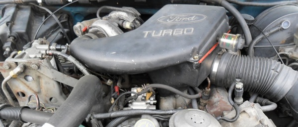
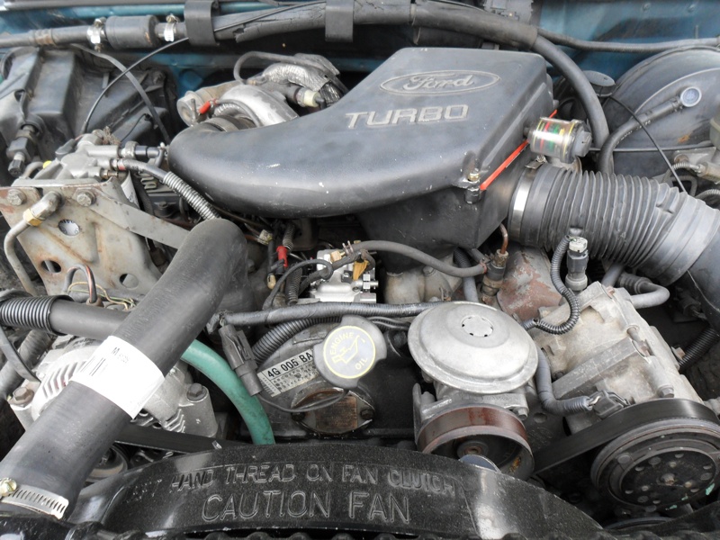
Something to point out here is Ford did not create the Power Stroke or it’s predecessor the 6.9L and 7.3L IDI (In-direct Injection) diesel engines. These engines were produced by International. The 6.9L was offered in the 3/4- and 1-ton Ford trucks from 1983 to 1987. The 7.3L followed from 1988 to 1993.
In 1993, the 7.3L was offered with a turbocharger to try to keep up with the Cummins. But, you have to remember,
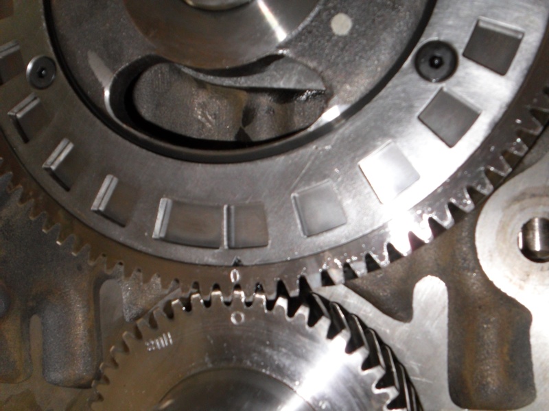
that is mounted to the camshaft gear. Notice the wider “window” on the target wheel and how this is referenced by the marks on the cam and crank gears to align cylinder #1 at TDC.
these IDI diesel engines were offered as a fuel efficiency alternative for the gasoline engines, not for high power output. Of course with Cummins leading the way, competition among the manufacturers was the name of the game. In 1994, Ford offered the 7.3L DIT (Direct-Injection Turbo) Power Stroke diesel engine. This engine hit the ground running and immediately started gaining everyone’s attention and trust. This engine was a totally new platform from the previous 7.3L. Contrary to what others may tell you, the only thing that these two engines had in common were bores and strokes. Everything else was totally different and would not interchange. Take a look at the tables below to get an idea of how the “Big Three” manufactures stacked up with diesel power in the early years.
Customer Demands
Because there were greater demands for more fuel economy, power and lower emissions in the 90s, International created the Power Stroke to meet these demands. By 1994 all diesel engines would be required to meet emissions demands by lowering the NOx (Nitrogen Oxide) gas coming from the tailpipe.
The 7.3L Power stroke would incorporate one device known as a DOC (Diesel Oxidation Catalyst) also referred to as a catalytic converter. With the engine being electronically controlled and a DOC, emissions demands along with power and economy could be met.
Here is how the Power stroke engine is designed and the functions that make it so unique. The Power stroke engine is also known as a HEUI (Hydraulically Actuated Electronically Controlled Unit Injection) design. This is where high-
pressure oil and electronics are used to control fuel injection timing and fuel pressure, which is very critical on a diesel engine. This way, the control of fuel timing would not be dependent on engine speed as in the case with mechanical injection pumps of IDI engines. Also, higher injection pressures are available throughout the entire operating range, from idle as well as higher RPM.
The HEUI system consists of five major components in order for the engine to operate properly. These are the PCM (Powertrain Control Module), IDM (Injector Driver Module), high-pressure oil pump, IPR (Injection Pressure Regulator), and the injectors.
The PCM monitors eight sensors from the engine and controls the operation of the fuel system. Each sensor generates a signal voltage from a specific engine function, which is relayed back to the PCM through the wiring harness.
The eight sensors are:
APPS – Accelerator Pedal Position Sensor
There is no throttle cable on this engine, this system is also known as “fly-by-wire.”
The APPS is attached to the accelerator pedal inside the cab. As the accelerator pedal is moved, the APPS will send
signals to the PCM with the driver’s demand for power. The PCM translates these signals to deliver the desired fuel quantity, injector timing and injection control pressure.
Attached to the accelerator pedal is what is known as an IVS (Idle Validation Switch). When the accelerator pedal is in the relaxed position, the IVS will send a signal to the PCM, which indicates that the driver foot is off the accelerator pedal and the engine will idle.
One safety feature to mention: If there is ever a controversial signal received by the PCM, meaning that the APPS is out of correlation, a fault will set and the engine will not accelerate, it will only idle.
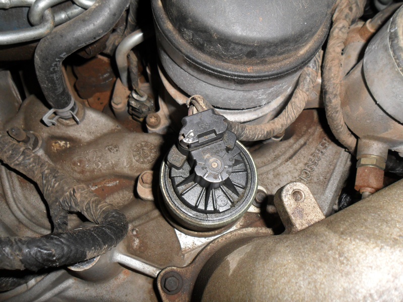
CMP – Camshaft Position Sensor
The CMP is a hall effect type sensor which is located in the front cover. On the front of the cam gear is a mounted target wheel slotted with windows. As the windows in the target wheel pass the CMP, a frequency is generated through the magnetic field of the CMP and received by the PCM. The frequency of the windows passing by the sensor along with the width of the window tells the PCM cylinder position along with engine speed. If the CMP is inactive, the engine will not fire.
ICP – Injection Control Pressure
The ICP sensor gives feedback to the PCM about the high-pressure oiling system. The ICP on the 7.3L is found installed in the high-pressure oil galley of the driver’s side cylinder head. The ICP is known as the “eyeballs” on the high-pressure oiling system. The signals sent to the PCM by the ICP determine the amount of high-pressure oil that is being supplied by the high-pressure oil pump to the injectors.
MAP – Manifold Absolute Pressure
The MAP sensor is a variable capacitance pressure-sensing disc that is mounted on the cowl near the right side hood hinge. It has a rubber hose coming from the sensor that is connected to the intake manifold.
When the turbo starts to boost and pressurizes the intake, the pressure pushes on the disc inside the MAP sensor to tell the PCM that more fuel quantity is needed.
EOT – Engine Oil Temperature
The EOT sensor is a thermistor that uses resistance to determine oil temperature. The PCM will read the resistance as in when the oil temperature increases, the resistance decreases.
This resistance provides temperature of the oil to the PCM so the PCM can tailor the fuel quantity, injection timing, glow plug operation, and exhaust back pressure. When oil temperature is below 122F, low idle is increased to 900 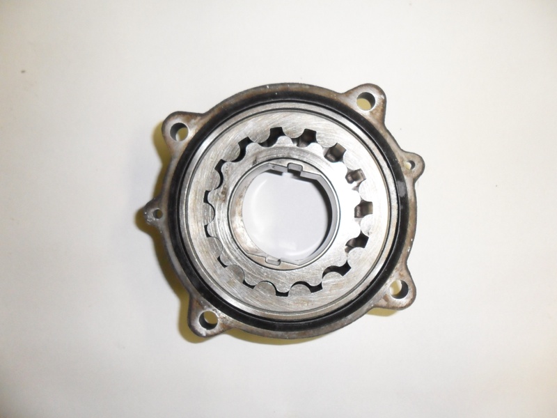 RPM for faster warm-up.
IAT – Intake Air Temperature
Mounted in the intake air cleaner and used to measure incoming air temperature through a thermistor to provide signals to the PCM. The PCM uses the IAT to enable the exhaust back-pressure control for faster warm-up.
BARO – Barometric Pressure
This sensor is located under the dash of the vehicle to measure atmospheric pressure, which the PCM uses to determine altitude. The PCM will use signals from the BARO to determine “glow-plug on time,” along with injection timing and control.
EBP – Exhaust Back Pressure
 The EBP sensor is mounted next to the high-pressure oil pump reservoir on the front of the engine and is connected by a metal tube to the right side exhaust manifold. The exhaust pressure enters the tube and is measured by the sensor. The sensor will send signals to the PCM about the pressure in the exhaust system.
The pressure in the exhaust is controlled by the exhaust back-pressure actuator used for warm-up purposes in cold weather. This sensor is the “eyeballs” for the PCM to control the exhaust back-pressure actuator.
Using these eight sensors, the PCM will control the engine’s performance with two actuators. The actuators receive electrical signals from the PCM, which in turn will move the actuator causing a change in controlled function.
The two actuators are:
IPR – Injection Pressure Regulator
The IPR is an electronically controlled pressure control valve. The IPR is mounted in the back of the high-pressure oil pump. In order for the engine to run, the high-pressure oil pump has to produce anywhere from 450 to 3000 psi of oil pressure. Depending upon the load of the engine, the IPR will be actuated to open and close which will increase or decrease the output of the high-pressure oil pump. The IPR is also known as the “hands” of the high-pressure oiling system. The PCM will use the “eyeballs” of the high-pressure oiling system, which is the ICP sensor to determine if the high-pressure oil requirements are being met for load conditions based on input from other sensors.
EBPR – Exhaust Back Pressure Regulator
The EBPR controls the actuation of the Exhaust Back Pressure Valve. On the exhaust side of the turbo there is flap mounted in a housing that can block exhaust gas from entering the tail pipe. This flap will close off the exhaust gas and increase back pressure on the engine to help aid in engine warm up in cold weather.
The EBPR is mounted in the turbo mount housing and uses lube oil that is directed to the turbocharger to control the movement of the exhaust back pressure valve. The PCM will open and close the exhaust back pressure valve by actuating the EBPR from information provided by the EBPS.
Injection Issues
As the PCM receives signals from the eight sensors and determines that the injector should be fired, the PCM sends a fuel delivery control signal to the IDM (Injector Driver Module). The IDM is basically a transformer box that sends a current pulse to energize the injector solenoid. The timing and duration of the IDM pulse is controlled by the PCM. When the IDM pulses the injector solenoid, the energy of the pulse is equal to 100 volts and 7 amps. On 1994 to 1997 models, the IDM is mounted under the hood against the driver’s side fender well. For the 1999 to 2003 models, because of the body design change, the IDM was mounted up underneath the driver’s side inner fender well next to the driver’s side door.
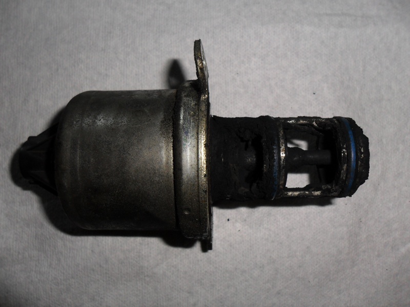
BELOW: Depending on operating conditions, the EGR valve would open allowing exhaust gas to enter the engine to be re-burned.
The injection cycle is very unique in the way that the fuel is directly injected and how the higher injection pressure is obtained. The injectors are placed in the cylinder heads so as the nozzle’s tip is near the middle of the combustion chamber in between the intake and exhaust valves.
Near the top of the cylinder head is a high-pressure oil galley and at the bottom of the cylinder head is a fuel galley. The injector has two chambers. The chamber at the top is for high-pressure oil to enter and the chamber at the bottom is for fuel to enter. When the engine is running, fuel has entered the lower chamber and is waiting to be compressed. The IDM energizes the injector solenoid, which opens the path for high-pressure oil that is surrounding the injector to enter the injector body. Inside the injector is what is known as an intensifier piston. Pressure builds on the intensifier piston, which pushes down on a plunger.
The downward movement of the plunger pressurizes the fuel beneath it in the injector, which causes the nozzle to open. Then fuel is sprayed into the cylinder. Something important to note about the injection cycle, the intensifier piston has a surface area that is seven times greater than the plunger.
When the engine is at idle, high-pressure oil pressure is around 500 psi. At wide open throttle, high-pressure oil pressures can reach 3000 psi.
So the injection pressure at idle that is being distributed at the nozzle would be: 500 x 7 = 3500 psi. At wide open throttle, the injection pressure out of the nozzle would be 3000 x 7 = 21,000 psi.
 This is what made the HEUI design more efficient than a rotary mechanical pump because of the fact that higher injection pressures could be reached and sprayed directly into the port.
Oil Outputs
The high-pressure oiling system that feeds the injectors gets its oil supply from the engine’s lube oil system. The engine’s lube oil system is broken down into two parts: a low pressure and high pressure system.
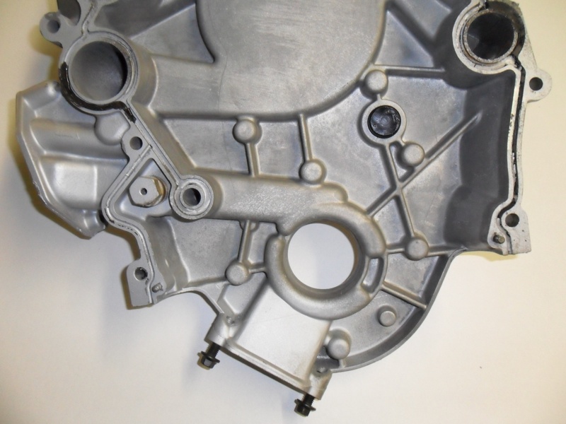
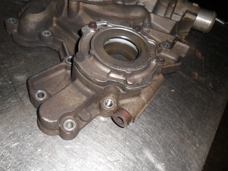
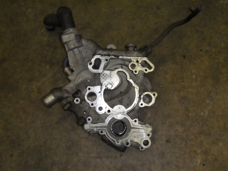
The low-pressure system consists of the engine’s lube oil pump, which is mounted on the front cover of the engine and driven by the crankshaft. As the crankshaft turns the gerotor style oil pump spins, which pulls oil from the oil pan through the pump and into the front cover.
Oil is then pressurized and sent through the engine’s oil cooler where it enters the oil filter. As oil exits the filter, it enters the oil galleries of the engine block to feed the main bearings, cam bearings, lifters, rocker arms, and turbo.
There is an oil galley inside the block at the front of the engine that splits off from the path that joins the galley where oil enters the oil cooler. This galley is the passage that delivers pressurized lube oil to the high-pressure oil pump (HPOP).
The HPOP is mounted in the valley in the top of the engine between the cylinder heads below the fuel filter basket. The HPOP is a pump that has a gear that is turned directly by the camshaft gear. As the HPOP turns it takes in low-pressure lube oil from the engine’s oil pump and “charges” it up to produce high-pressure oil. The HPOP is basically a hydraulic pump that then distributes this high-pressure oil to the cylinder heads by high-pressure hydraulic hoses. High-pressure oil is now being distributed to the cylinder heads waiting to enter into the injectors. The HPOP pressure is controlled by the PCM using the ICP to see what pressure is in the cylinder head and the IPR to increase or decrease this pressure depending on the demands being placed on the engine from the eight sensors sending information to the PCM.
Expiration Dates
Now that there has been a crash course on how the 7.3L Power Stroke engine functions, we can examine why it became extinct. The race among the manufacturers was in full swing to bring their diesel engines up to compliance by the year 2004. Even though the 7.3L did landmark the Ford truck, the engine would fail to be emissions compliant for 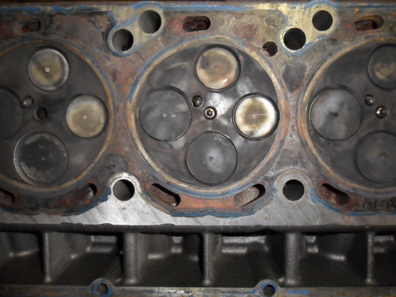 2004.
2004.
NOx gas being emitted from mid-size diesel engines was still the target. A second tier of emissions regulations were going into effect and efficiency would also become a factor. The easiest solution at this time to lower NOx gas was the use of the EGR (Exhaust Gas Recirculation) valve.
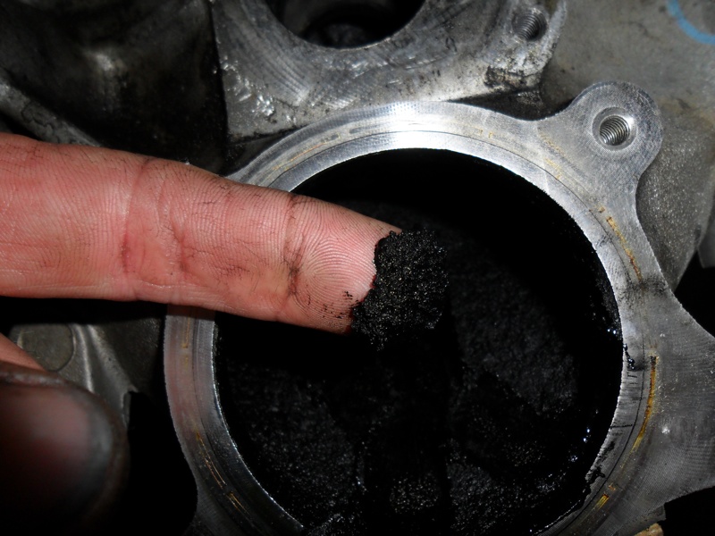
Under normal operating conditions when exhaust gas is re-introduced into the engine, NOx gas is reduced. The problem is exhaust gas lowers the efficiency. When the engine is running, oxygen is entering the turbo and compressed into the engine’s cylinders. The diesel fuel is injected and the flame front produces a tremendous amount of heat. If the EGR valve is open, the exhaust gas has displaced the oxygen entering the cylinders and lower combustion temperatures occur. This effect may lower NOx, but the trade off is incredible.
Not only do you get a cooler burn so the efficiency drops, but soot becomes a problem. Lower combustion temperatures produce soot, which tends to clog everything up. Even though there has never been any statistics released on the engine’s efficiency drop from EGR, some research has proved that there can be as much as a 3% power decrease. All though the 7.3L was a reliable engine, it was not all together efficient. Introducing exhaust gas back into the 7.3L would prove to be disastrous in trying to overcome emissions regulations. In order to meet these demands, International took a whole new approach and invented the 6.0L Power stroke.
New Kid on ‘The Block’
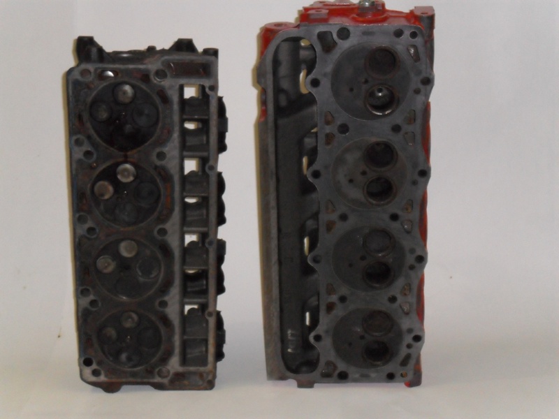
Unique would be a good way to describe it, because now the engine was smaller.
The stroke was increased and the bore decreased from that of the 7.3L. Not only was the engine smaller with 365 cubic inches, but the engine was totally revamped. Changes included different engine gear train, cylinder heads, turbo, injectors, HPOP oiling system, more sensors and actuators, and an EGR cooler and EGR valve.
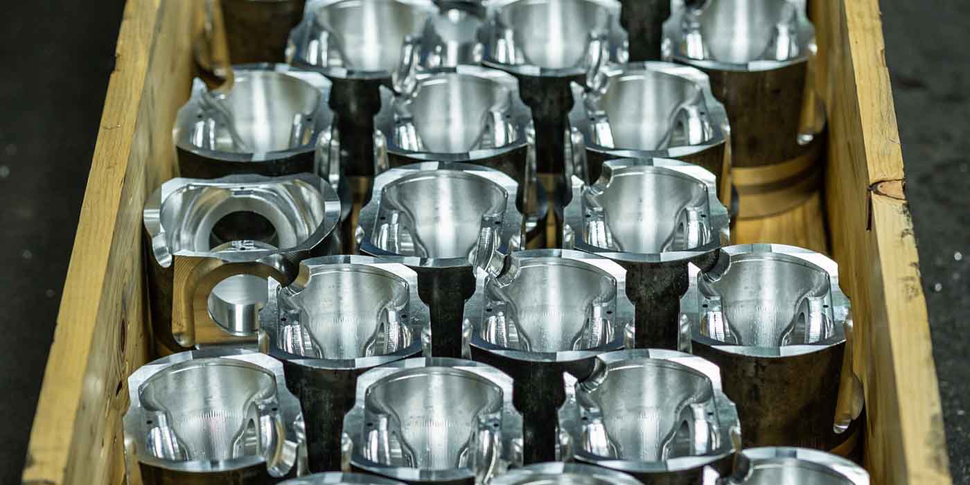
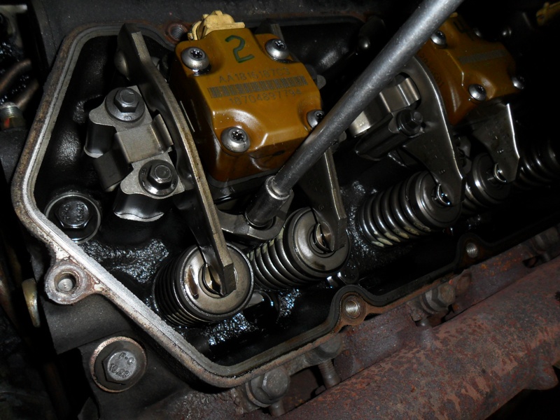
For most applications, improvements for any engine come from cylinder head modifications. Now for the 6.0L, the cylinder head would have four valves per cylinder. There are two intake valves each measuring 1.33” and two exhaust valves each measuring 1.10”. But, the valves were placed in the cylinder head in a “twisted” fashion with two separate intake runners per cylinder.
The reason for the “twisted” position was to help introduce swirl into the combustion chamber.
Remember, the combustion chamber is part of the piston bowl. The higher the port swirl is in the combustion chamber, the more efficiently diesel fuel will ignite. This also helps reduce the “knocking” sound that older diesel engines produced when the fuel was ignited. With swirl being increased, the piston bowl was changed so that it was centered in the top of the piston. The 7.3L piston bowl was offset because there were only two valves per cylinder  positioned in the lower part of the cylinder head.
Engine Engineering
The high-pressure oiling system was also changed. For the 7.3L, the HPOP was in the center of the engine underneath the fuel filter basket and gear driven by the camshaft gear in the front of the engine which was driven by the crankshaft gear. The HPOP had high-pressure lines that feed “barrel” passages in the cylinder heads.
For the 6.0L, there are no “barrel” passages in the cylinder heads. The high-pressure oiling system is totally contained in the engine.
The problem seen in some instances with the 7.3L was the high-pressure lines coming from the HPOP would crack or break. When this happened, high-pressure oil would spray the entire engine compartment and quickly empty 15 quarts of oil from the crankcase.
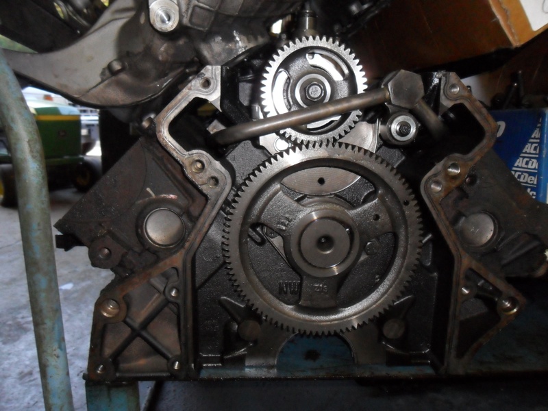
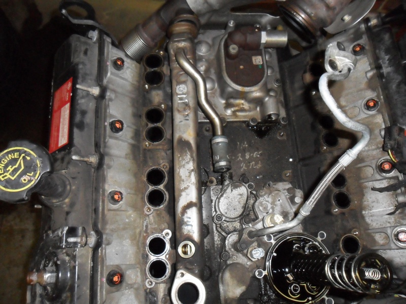
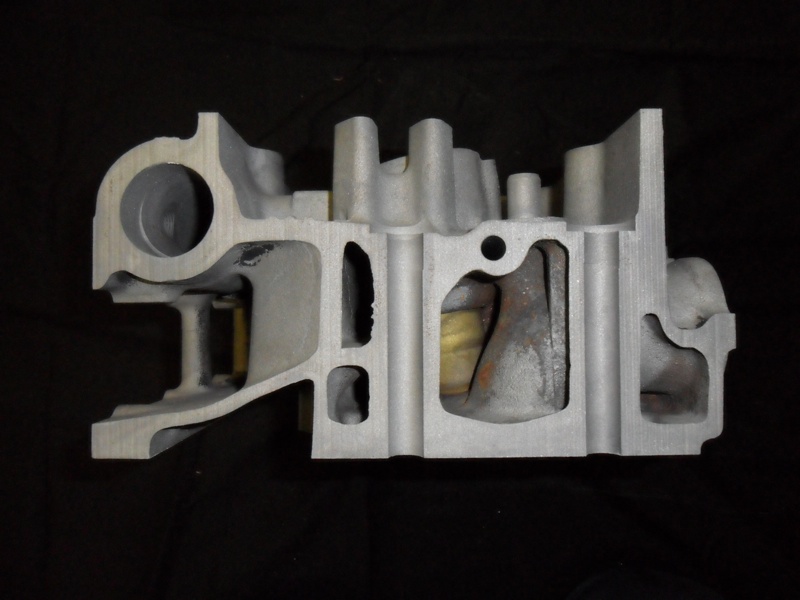
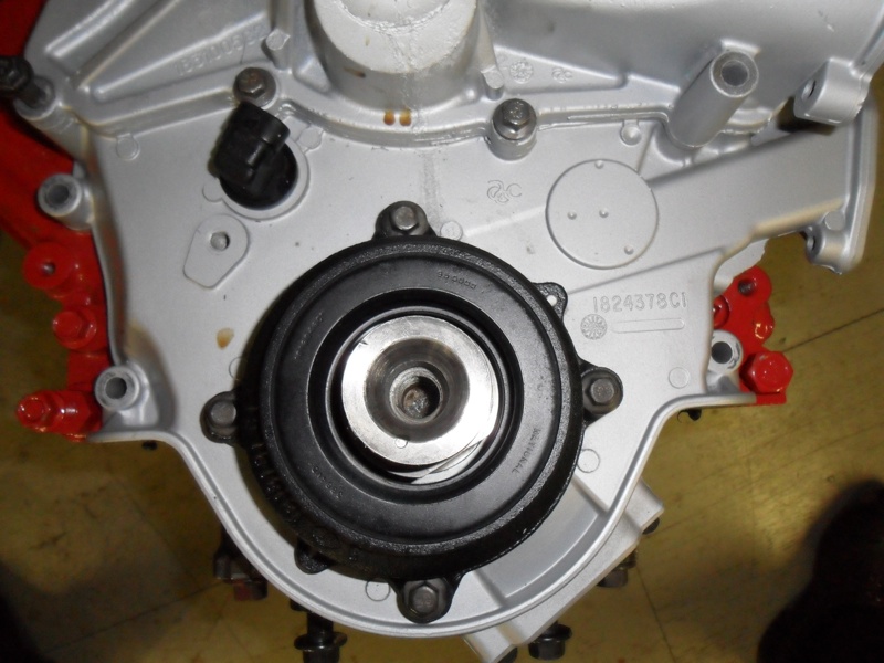
ABOVE #2: The HPOP is placed under a cover at the rear of the engine and driven by the gear-train.
This could also be a fire hazard if the engine was under heavy acceleration where the exhaust system can get extremely hot. In the 6.0L, the HPOP is driven by the camshaft, which in turn is driven by the crankshaft. This gear train is now in the rear of the engine. The HPOP is positioned in a compartment in the top of the engine at the rear of the block.
Hydraulic steel lines run in the block from the pump to fittings in the lifter valley. These steel lines are also known as “branch tubes.” From fittings in the lifter valley there are standpipes that carry the high-pressure oil to the cylinder heads. The standpipes connect to an oil rail or bladder that sits in the top of the injectors.
The fuel passages in the head are similar to that of the 7.3L where it is delivered through a galley in the cylinder head where it feeds the lower portion of the injectors.
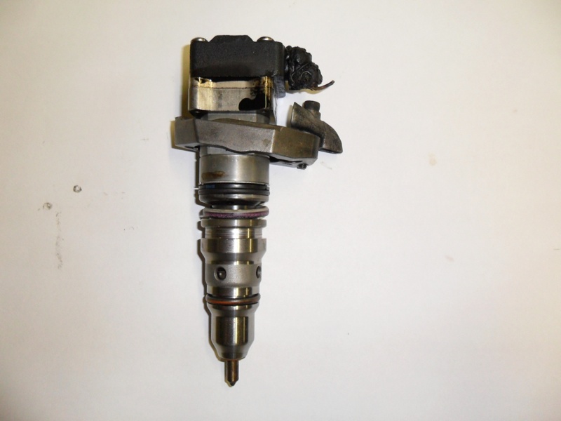
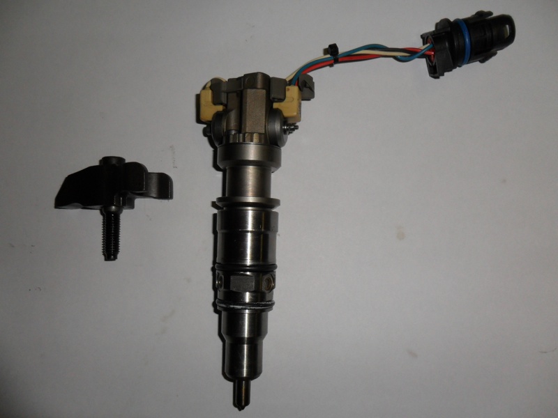
The injectors for the 6.0L are very different from that of the 7.3L. The 6.0L injector is still a HEUI design, but in a very compact way.
On the 7.3L, when the solenoid was energized, this opened a passage that allowed high-pressure oil in to act on the intensifier piston. The internals of this injector where spring loaded so after the injection cycle started and completed, the springs being compressed would return the working mechanisms inside the injector to a closed position to get ready for the next cycle. The 6.0L has two working coils per injector that operate at 48 volts each. One is to open the spool and one is to close the spool.
 The spool, when energized, has to move .015” within a matter of milliseconds to allow high-pressure oil into the intensifier piston. When the “open” solenoid is energized the spool will move to allow high-pressure oil in. The PCM controls how long to hold the “open” solenoid energized and then actuates the “close” solenoid to return the spool to the closed position. By using two solenoids, the injector’s body could be made smaller.
Since the cylinder heads have four valves per cylinder, the small bodied injector could be placed in between the four valves in the center of the cylinder. The internal mechanisms of this injector are also spring loaded, which will return their internals to a closed position for the next injection cycle.
Something to note here is that under full throttle, the coils on the injectors can actuate 27 times a second. The voltage to actuate the injectors on the 6.0L comes from the FICM (Fuel Injection Control Module).
The FICM is controlled by the PCM based on inputs from the engine’s sensors. The FICM is located on a bracket that is fastened to the top of the driver’s side valve cover.
 Adding Sensors
Now for the 6.0L engine, there are more sensors and actuators that are used by the PCM than that of the 7.3L. The reason for the increase in the electronics is for more control of the engine.
Demands for more specific fuel calibration become a factor when the object is to lower emissions. Additional sensors and actuators provide more feedback and the ability for more precise control of engine functions. In addition to the eight sensors found on the 7.3L, the 6.0L has four additional. Also, there are three more actuators controlled by the PCM.
The four additional sensors are:
ECT – Engine Coolant Temperature
This is a thermistor type sensor used by the PCM to read the temperature of the coolant. The PCM uses the resistance

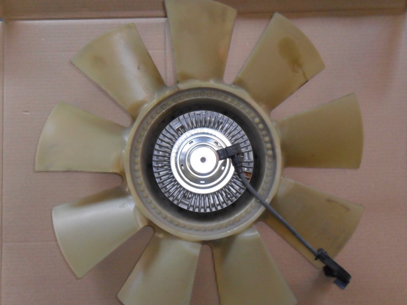
changes of the sensor as the coolant is cold and then heated to operating temperature to tailor fuel calibration. The PCM also monitors the ECT for coolant fan clutch operation. The 6.0L has an EVFC (Electronic Viscous Fan Clutch) which is a part of the coolant fan assembly. With the use of the EVFC, the fan can free wheel when coolant temperatures are cold so less air can be pulled into the radiator.
When coolant temperatures increase or the A/C is turned on, the PCM can pulse the EVFC, which will engage the clutch to spin the fan.
CKP – Crankshaft Position Sensor
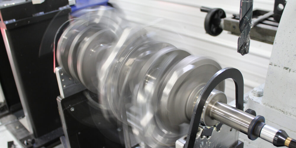
The CKP is a hall-effect type sensor that is used to read a target wheel that is mounted on the crankshaft. The target wheel is also known as a 60 minus 2.
The target wheel has 58 teeth mounted on a steel disc that is bolted to the crankshaft. There is a gap in the target wheel that is where two of the teeth are missing. As the target wheel passes the CKP there is a break in the magnetic field, which relates crank speed and position relative to TDC to the PCM. The CKP also is in sync to the CMP for proper cylinder firing and detection for a cylinder misfire.
EGRVP – Exhaust Gas Recirculation Valve Position
This sensor is a potentiometer that is a part of the EGR valve. The EGRVP relays information to the PCM concerning
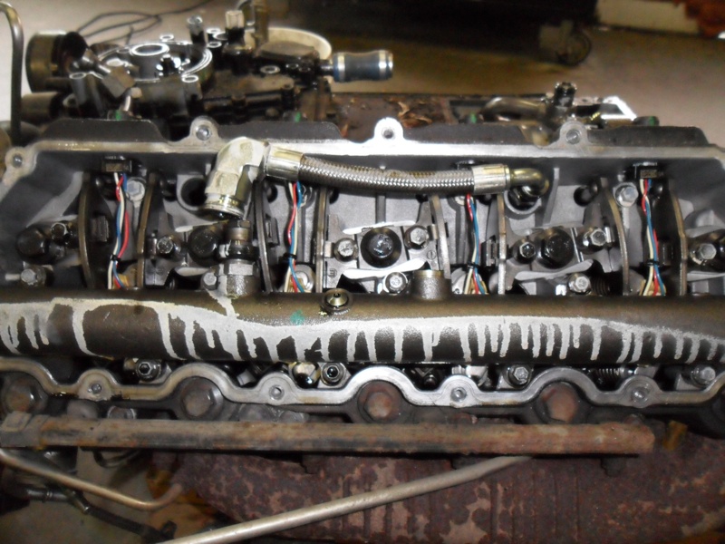
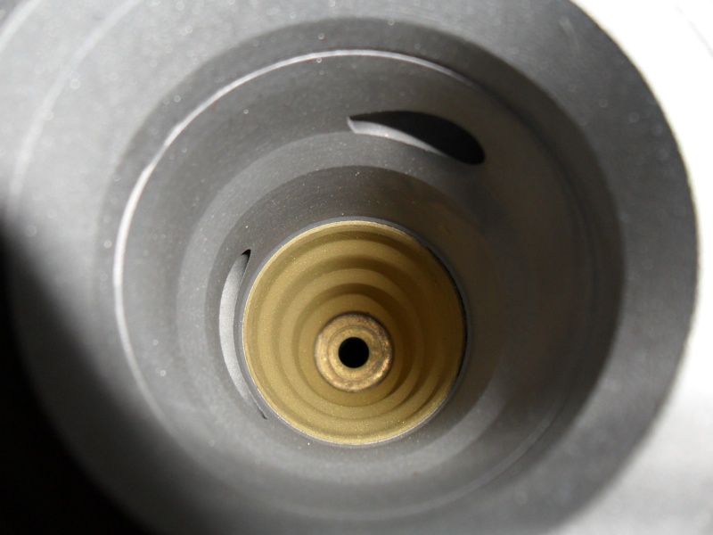
BELOW: Later year models had redesigned high-pressure oil rails which were a “bladder” style which were more efficient in supplying high pressure oil.
how far the EGR valve is open. This way the PCM can monitor proper EGR function.
MAF-Mass Air Flow
The MAF is mounted in the air intake tract between the air filter and the turbo inlet. The body of the MAF consists of a module that houses a heated wire. As air passes across the heated wire, it cools the wire. The wire is heated to approximately 392F above ambient temperature and the PCM monitors the voltage needed to keep the wire heated to this temperature. This voltage measurement tells the PCM the amount of air that is being taken in by the engine. This sensor also helps in more precise fuel calibration of the engine. Inside the module of the MAF is also another sensor known as IAT#1 (Intake Air Temperature #1). Same as the 7.3L, where incoming ambient air temperature is measured for the PCM.
IAT (2) – Intake Air Temperature Sensor #2
This is also a thermistor type sensor mounted in the intake manifold. The sensor will change resistance with air temperature changes. This sensor is used by the PCM to determine if the compressed air inside the intake manifold is satisfactory for the operating conditions at the specific time. Also used by the PCM for more precise fuel calibration.
The three other additional actuators are:
EGR – Exhaust Recirculation Valve
 In order to lower emissions, the EGR valve opens and allows exhaust gas to enter the engine to be re-burned. When conditions are optimum for EGR valve operation, the PCM will command the valve to open at a specific rate. The PCM uses the EBP and the EGRVP to control how far the valve needs to open for the current operating conditions. Before exhaust gas can enter the intake manifold on a diesel engine, it must be cooled.
Exhaust temperatures for a diesel engine can be in the range of 1200F or more under load. In order to cool the exhaust gas entering the intake, it must pass through an EGR cooler.
This is basically a small radiator that is mounted between the exhaust pipe and intake that has flues and fins that engine coolant is circulated through to cool the incoming exhaust gas.
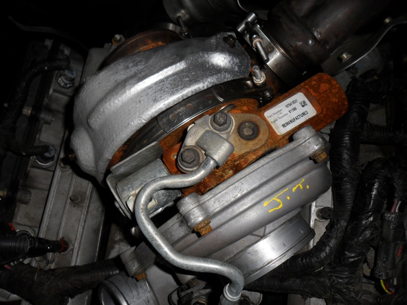
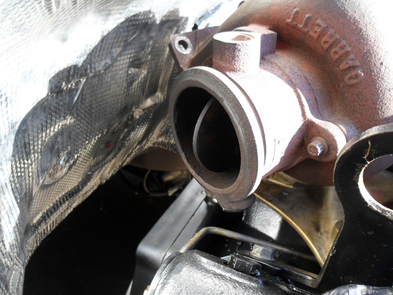
VGTCV – Variable Geometric Turbo Control Valve
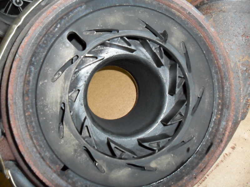
The turbo on the 6.0L has a series of veins in the exhaust housing. The veins are mounted to a unison ring that will rotate a small degree in either direction. When the unison ring moves, depending on which direction, the veins will either open or close.
The veins will direct exhaust gas flow inside the turbine housing to push upon the exducer wheel of the turbo.
How fast the turbo can spool is dependent on where the exhaust gas pushes on the exducer controls .
This allows lower RPM turbo operation for quick response and also top end acceleration at higher engine speeds. The purpose of the Variable Geometric Turbo Control Valve is to move the unison ring in order to move the veins.
The VGTCV is mounted in front of the turbo and uses the engines oil pressure that is used to lubricate the turbo to move the unison ring. It is basically a hydraulic valve where it takes oil pressure and turns it into a working fluid for turbo actuation.
GPCM – Glow Plug Control Module
The GPCM is a solid state type relay that is mounted at the front of the passenger’s side valve cover. The glow plugs are needed in cold weather conditions to warm the incoming air in the combustion chamber. The warm air makes for easier starting and less smoke in cold weather start up.
The GPCM is used by the PCM to supply voltage to the glow plugs when they are needed and monitor how long they are engaged. The GPCM also sends feedback to the PCM when one or more of the glow plugs become shortened and no longer functions.
 Even though the 6.0L does have more sensors and actuators that give the PCM more control over the engine’s functions, the engine is more efficient. With the different bore and stroke along different design of cylinder heads and injectors, the engine is still an effective HEUI design.
But, the 6.0L leads the trail on engine repair costs among diesel engines from 2003 to 2007. These engines have been plagued with repairs such as blown head gaskets, sticking injectors, and stuck veins in the turbo, failing FICM, and leaking EGR coolers.
After a few run ins with some of the above mentioned repairs, owners often end up selling the vehicle before they get in too deep.
I can’t say that I blame them. The 6.0L can become a money pit. Although they made more power and torque versus their size and cubic inch, they could not live up to the reliability of the 7.3L.
Over the course of its four years in existence, the 6.0L underwent quite a few changes to help improve reliability.
Here are some examples of the changes for the 2004 and 2005 model year.
2004
• New piston bowl design to improve emissions
• Glow Plugs were shortened by 1.2 mm to accommodate the new pistons
• New camshaft design
• Water pump impeller was increased from 90mm to 100mm
• New FICM bracket with upgraded isolators to help in vibration
• New high-pressure oil rail design to reduce engine noise and improve fuel economy by reducing pressure drop to injectors
• Revised HPOP to meet the demands of the new high pressure oil rails
• ICP sensor relocated to the front of the passenger side head
 • Cross-over section on the back of the intake manifold was eliminated
• EGR throttle blade eliminated
• Square EGR cooler to replace the round design
• Three fins were added to the turbo compressor wheel
2005
• Peak torque changed from 560 lb.ft. to 570 lb.ft.
• Turbocharger bearing size increased
•Revised HPOP
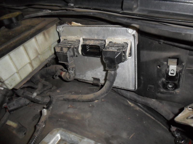
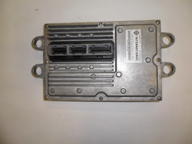
BELOW: The FICM is bolted to a bracket on top of the drivers side valve cover. The FICM produces the 48 volts that when commanded by the PCM, will open and close the injectors.
• New high pressure oil rails for the cylinder heads. The ball tubes that sit in the injectors from the high pressure rails were made 2mm longer. These are not interchangeable with earlier 2004 version
• EGR valve was improved
• A “scoop” was added to the exhaust up pipe to smooth out exhaust gas flow to the EGR cooler.
• The EGR throttle blade was eliminated. For previous years, a throttle blade was placed in the intake which would close when the EGR valve was open.
The blade was placed in the intake to help siphon in exhaust gas in under EGR valve actuation. It was later determined that the blade was of little help.
Wrapping Up
Something to mention here is that the 6.0L Power Stroke diesels are often associated with premature head gasket failure.
Head gasket failures often result in engine damage due to leakage of combustion gasses into the engines cooling system. Some engines have seen combustion leakage as early as 50,000 miles. Most of these engines see heavy loads and severe service life in which the original multi-layer steel gaskets tend to fail.
Federal-Mogul has introduced a head gasket that has been engineered for the 6.0L Power Stroke to address the sealing concerns with OE gaskets.
 These gaskets are multi-layer steel construction with an advanced embossment design that creates increased spring force and more robust sealing contact under extreme loads. Also, these gaskets address premature push rod wear leading to oil contamination associated with OE gaskets by making the pushrod holes in the gasket over-sized and coating the guide holes with a non-abrasive material.