 Clean, smooth and flat have always been requirements for proper head sealing whether you are building a stock engine or a monster motor for a ProStock drag car. Head gaskets can only accommodate so much distortion and roughness across the face of the cylinder head and deck. Soft faced composition gaskets can obviously tolerate more imperfections than a Multi-Layer Steel (MLS) head gasket, but they have limits, too. A surface that is too rough may have too many scratches and deep crevices to prevent a leak-free seal. A surface that is too smooth may not grip and support a composition gasket adequately. And if the surface is not flat enough, the gasket won’t be loaded evenly, which can lead to leaks and premature gasket failure.
Resurfacing the desk surface on a cylinder head and/or engine block should restore flatness and achieve the required smoothness provided the procedure is done correctly (not too fast, not too deep of a cut in one pass, and making sure the tool bits are sharp and mounted correctly in the milling head).
With late-model production engines that have relatively thin deck surfaces, you are often limited as to how much metal you can safety remove before you weaken the casting or increase compression too much. With overhead cam engines, milling a head or block alters camshaft timing so again you are limited as to how much metal can be safely removed. If you have to go beyond the factory limits, you can compensate by installing a thicker aftermarket head gasket or even using a copper or steel head gasket shim to restore head height back to its original dimensions.
Aftermarket cylinder head and block castings typically have thicker deck surfaces than stock counterparts, so you have more metal to work with if surfacing is needed to achieve a certain deck height or compression ratio. A thicker deck surface also provides additional strength and rigidity for the casting, which is a plus in high horsepower applications.
If you are rebuilding a late model OHC engine with an aluminum head, it’s not unusual to find a lot of distortion in the head. Overheating tends to bow the cylinder head up in the middle because heat concentrates in the center of the casting. This, in turn, may bind or even bend the camshaft(s), cause increased cam bearing wear and cam bearing misalignment in the head. If an OHC cam has seized or is broken, it’s a sure bet the head is warped and will need to be machined or straightened to restore flatness as well as cam bore alignment.
Straightening
Head straightening is often the preferred technique for correcting an OHC head that is out-of-flat or has misaligned cam bores. If you can straighten the head first, and then machine it, it will minimize or possibly eliminate the amount of milling that you will have to do to restore flatness on the deck surface.
The maximum acceptable limit for out-of-flat on the deck surface of a cylinder head or engine block will vary with the application and type of gasket.
For a pushrod engine with cast iron heads, out-of-flat should generally be .003 in. (0.076 mm) or less for a V6 head, .004 in. (0.102 mm) or less for a V8 or four cylinder head, and no more than .006 in. (0.152 mm) in a straight six cylinder head. Aluminum heads and performance applications should be even flatter – no more than .002 in. (.05 mm) out-of-flat in any direction and less than .001 inches out-of-flat across a three-inch span in any direction. If you want it to seal, it has to be as flat as you can get it.
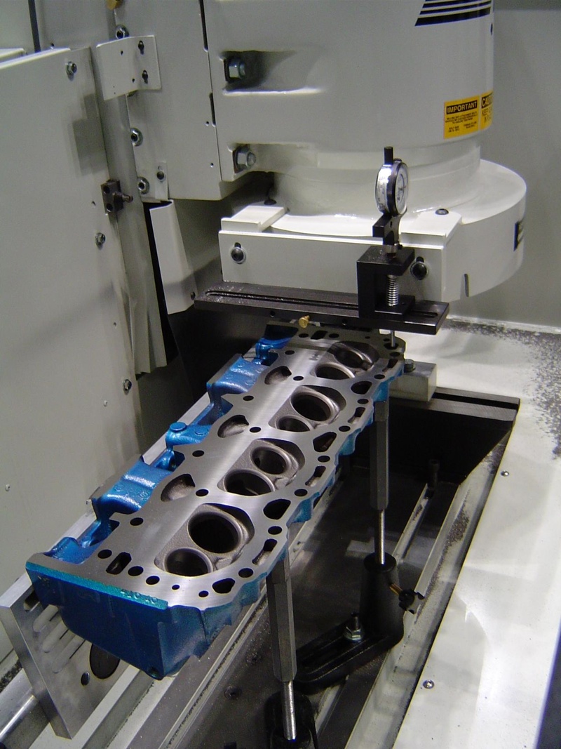
Distortion and wear in the cam bores of heads with overhead cams is critical, so bore alignment must be checked with either a straight edge and feeler gauge or dial indicator. If the bores are off by more than .003 to .005 inches, line boring or head straightening will be required to restore proper cam bore alignment.
One of the tricks to successfully straightening a warped OHC aluminum head is to straighten the cam bores first. Once the cam bores have been realigned, chances are most of the distortion on the deck surface will also have been eliminated.
Straightening requires measuring (to determine how much the cam bores are misaligned and/or the deck surface is out-of-flat), then counter shimming and bolting the head to a heavy steel plate to offset the distortion, then using heat to stress relieve the head so when it is unbolted from the steel plate it will hopefully be much straighter and flatter than before. The shims under either end of the head should equal half the total warping.
Bringing the Heat
Once a head has been shimmed and bolted to a heavy steel plate (one-and-a half-inches thick or thicker for rigidity), the head and fixture can be placed in an oven and heated to 450 to 500 degrees Fahrenheit for four hours.
Don’t go any hotter or you run the risk of annealing (softening) the casting. Once the oven cycle is complete, allow the head to slow cool back to room temperature. Slow cooling is best because it reduces the risk of stress cracking.
How much cam bore misalignment or out-of-flat can you correct using a thermal straightening process? You can usually correct as much as .030 to .040 inches of misalignment or out-of-flat with a single treatment.
We’ve heard of some machinists correcting as much as .090 inches of warping by using multiple treatments to gradually straighten a head.
We’ve also seen people use a rose bud torch to spot heat a cylinder head to correct cam bore misalignment and warping. This technique is more of an art and requires a fair amount of experience to do successfully. That’s why the shimming method is usually preferred.
Surface Finish
The surface finish that’s required will depend on the type of head gasket. Though Ra (Roughness Average) has traditionally been used to describe surface finish, most gasket engineers today say a more accurate perimeter is Rz, which is the average difference between the peak height and valley depth. Ra can have a wide variance across a given surface profile, so Rz gives a better indication of the actual texture across the surface.
To measure Ra or Rz, you need a profilometer. If you don’t have one, you are shooting in the dark and assuming the surface finish you’re getting is in the ballpark. Maybe it is and maybe it isn’t.
The only way to know for sure is to actually measure it. Most dry milling machines with the proper CBN or PCD cutting bits can achieve an extremely smooth surface finish.
If you are building a street performance engine that has a cast iron block and aluminum heads, and are using conventional steel/fiber composite head gaskets or expanded graphite head gaskets, the surface finish should ideally be 60 to 80 Ra (360 to 480 Rz).
Don’t go smoother than 40 Ra (240 Rz) or rougher than 100 Ra (600 Rz) with a composition gasket. Rougher surfaces limit gasket conformance, while smoother surfaces increase the tendency for gaskets to flow, reducing the gaskets blow out resistance.
MLS head gaskets are made of several layers of embossed stainless steel (most are 3 or 4 layers thick, but some have more). A thin coating (.001 to .0015 in.) of nitrile rubber or Viton is used on the external surfaces as well as between the layers to provide maximum sealing.
Most aftermarket MLS gaskets can handle surface finishes as rough as 60 to 70 Ra micro inches, but some specify a smoother finish of 30 to 50 Ra. Smoother is always better, and if you can get the finish down to the low teens or even single digits, great! But for most applications, a surface finish in the 20 to 30 RA range (120 to 180 Rz) is more than smooth enough for a performance MLS gasket.
Waviness across the surface is also important. The less waviness the better: no more than .0004 inches with MLS head gaskets. Trouble is, you can’t measure waviness with a profilometer. It takes special (expensive) lab equipment. Waviness problems can be caused by vibrations and a lack of rigidity in milling equipment.
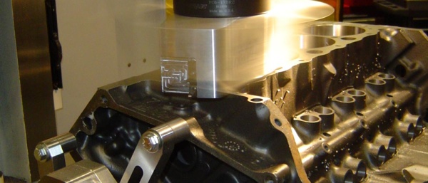
Dry milling is pretty much the only acceptable way to resurface late model cylinder heads and blocks and castings for racing applications. A belt sander, broach or grinder may have been good enough for resurfacing stock Chevy 350 heads years ago, but not for today’s engines or for performance applications. You can’t get the precision and smoothness that today’s engines require with outdated equipment and tooling. Productivity also suffers when you are using older, slower machines that can’t compete with today’s high-speed re-surfacing equipment.
Some surfacing equipment can be set up and mill a head in five minutes or less. What’s more, if you are resurfacing several identical heads in a row, the actual milling time may only be a couple of minutes. It all depends on the speed of the cutter head, the number of tool bits, the feed rate and how smooth you want the surface finish to be.
Most of today’s high-speed surfacers are designed to use CBN or PCD inserts in the cutter heads. CBN works best on cast iron, and PCD is best for aluminum.
Aluminum tends to stick to CBN, which can smear the surface of the head or block you are milling. Even so, many shops use CBN on both cast iron and aluminum successfully by using a light oil (such as olive oil or even furniture polish) to prevent the aluminum chips from sticking when milling with CBN. This also eliminates the need to change your tooling if you are resurfacing both cast iron and aluminum heads on the same machine.
Carbide can also be used for resurfacing cast iron or aluminum, and costs less initially than PCD or CBN. But its shorter tool life means you have to replace the tooling more often, which actually increases your costs over the long run. CBN inserts in a milling machine will typically cut up to 50 times as many heads as carbide inserts before they have to be changed. The increased longevity of CBN improves consistency from one job to the next and reduces down time for tooling changes.
Because CBN and PCD are designed for high-speed milling, replacing the carbide inserts in an older surfacing machine won’t necessary achieve all the benefits that these super abrasives are capable of delivering – especially if an existing surfacing machine lacks the horsepower, rigidity or adjustability to operate at higher spindle speeds. Rigidity becomes a factor as operating speeds increase. A machine that lacks the required rigidity can’t deliver ultra smooth finishes at high speed because there’s too much movement between the work piece, table and cutter head.
For example, a converted grinder may be able to mill heads and blocks. But the spindles and table drives in many of these older machines cannot hold close enough tolerances to achieve a really smooth, flat finish. You are better off investing in new, high-speed milling equipment that has been designed from a clean sheet of paper for PCD and CBN tooling.
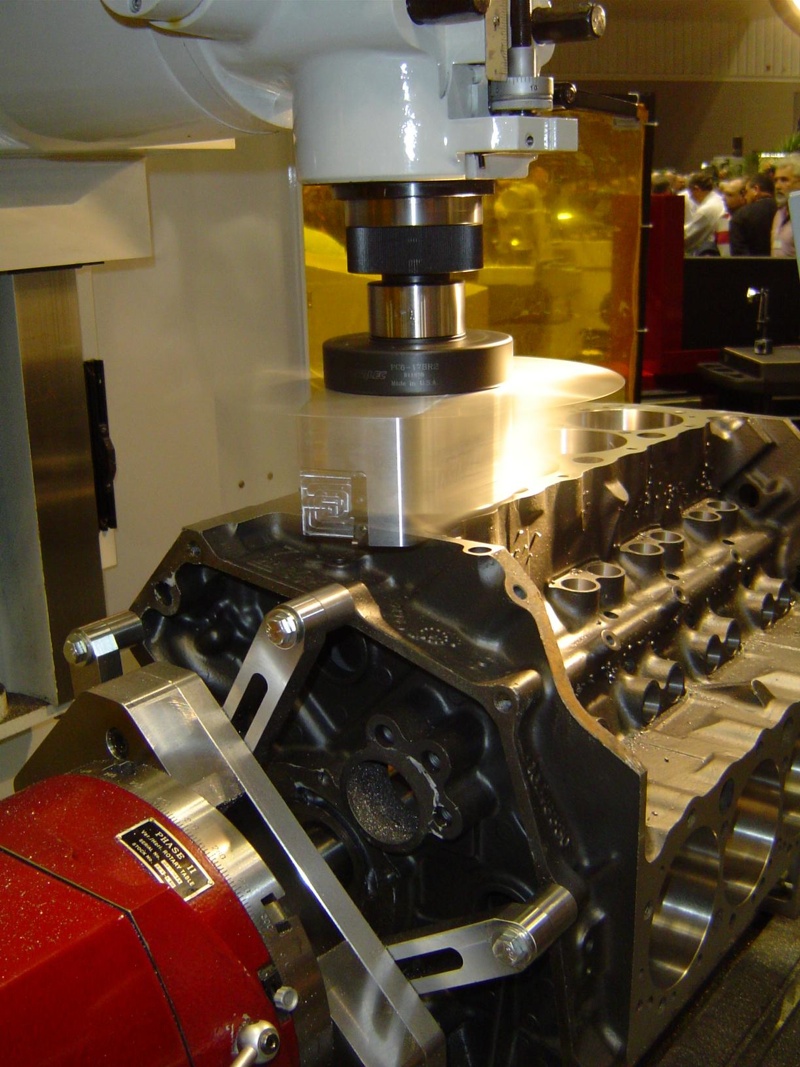
Regardless of what type of resurfacing machine you use, make sure the fixturing is level and true to the cutting head, and that the cylinder head or block is mounted squarely in the fixturing before you start cutting metal. If the work piece is not correctly aligned in the fixturing, you obviously won’t get a straight cut.
Automated resurfacing equipment with CNC controls can save time, improve accuracy and consistency, and reduce mistakes. Single insert cutting heads are perfectly adequate for most resurfacing work, but cutting heads with multiple inserts can handle higher speeds and feed rates.