 Choosing a particular type of camshaft for an engine build is an important decision that has to be made before any other parts are ordered or machined. Choosing a cam requires answering some basic questions, the most important of which is the engine application itself.
Are you building an engine for everyday driving? For towing? For street performance? For street/strip? For drag racing or a circle track car? Are there class rules that limit the type of camshaft and valvetrain components that are allowed?
What kind of vehicle is the engine going into (light car, heavy car, truck, race car)? What kind of transmission and gearing will the vehicle have (stick, automatic, wide ratio or close ratio transmission gearing, final drive ratio)?
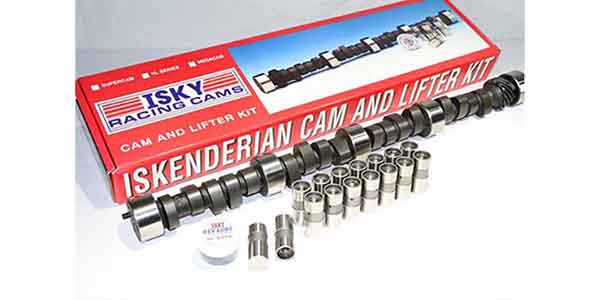
How much money is your customer willing to spend on the cam and valvetrain? Is it a budget build that will require a flat tappet cam with solid or hydraulic lifters, or is the sky the limit?
The camshaft determines the engine’s horsepower and torque curves, so the cam has to match not only the application but all of the other components that go into the valvetrain, the cylinder heads, compression ratio and induction system.
It is important for engine builders to seek out as much information from the customer on the build as they can. Sometimes, these details can come from familiarity of performing engine builds at different levels.
“There is no substitute for experience when it comes to matching the cam to the application. An engine builder who is very familiar with the type of engine and application will have valuable insights into camshaft selection which really cannot be acquired any other way,” said one camshaft manufacturer.
“One specification may appear to be optimal, but often there are other considerations which will effect the on-track performance of the engine in important ways.”
Another manufacturer/supplier explained when it comes to performance street cars, nearly everyone with a small block Chevy wants it to be capable of at least 6,000 rpm.
“That doesn’t sound too radical but in a car with 3.08 gears, 26-inch tall tires and a 400R4 auto trans, that results in an overdrive ratio of 2.16. That will equal 1650 rpm @ 60 mph. That MAY be acceptable on really flat land. In hilly country with some long grades, it may not have enough torque to stay in overdrive on the grades. Even a 3.90 ratio = 2.73 final gearing which 60 mph = about 2300 rpm. If significant grades are involved 6000 rpm should not even be considered.
Incidentally 6000 rpm in 3rd gear, Direct drive, = 120 mph with the 3.90 gear and 150 mph with the 3.08 gear.
Most cams larger than stock are capable of 6,000 rpm, even if peak power is much lower. Rarely is anyone going to spend much if any time over 100 mph.”
Over Cam Issues
When it comes to picking the camshaft, one of most commonly made mistake is over-camming the engine with too much lift and/or duration. Big numbers look impressive, and you may have a customer who insists having the wildest cam he can find for his engine. But is it the best cam for how he will actually use his vehicle? Probably not.
Most street driven vehicles seldom see the high side of 5,500 rpm, and most cruise at 1,800 to 2,500 rpm on the highway depending on how they are geared. The best all-around cam for a street performance vehicle, therefore, would be one that has its peak power and torque curve in the 1,500 to 3,000 rpm range.
On the other hand, if you are building an all-out race motor for a customer’s race car, you’d want a cam that produces peak power and torque in the rpm range where the car will be running most of the time.
“When in doubt, it is almost always better to go with what you might think is slightly less cam than you need as opposed to slightly more. Too much cam will usually hurt drivability far more than too little will,” said one manufacturer of camshafts.
As for lift, most stock and lightly modified heads won’t flow any more air once valve lift reaches about 0.550˝. Pushing the valves open any further will not increase airflow or power, and may actually hurt power because of reversionary air flow. On the other hand, if you’re building a Pro Stock race motor with highly modified heads and CNC huge ports that can handle gobs of air, increasing valve lift to the physical limits of the engine is often necessary to maximize power.
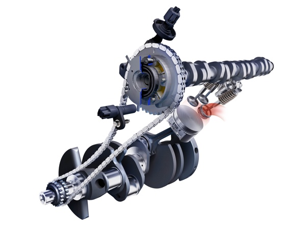
Another decision that has to be made is how much lift do you want from the cam and rockers? For any given lift, you can use various combinations of cam lift and rocker arm ratio to achieve the same numbers.
According to one cam supplier we interviewed, the best approach is to get more lift with the rocker arms and less with the cam. Why? Because higher lift cams are more highly loaded cams that experienced more wear.
Consequently, you are more apt to round off a lobe on a high lift cam that has big lobes than one which uses smaller lobes with higher ratio rocker arms. The valvetrain also tends to be more stable when a higher percentage of the valve lift is generated by the rocker arms rather than the cam lobes, lifters and pushrods.
Picking Performance
One camshaft manufacturer provided these tips for selecting a performance camshaft for stock cars, dragsters and road racers.
• Stock Car Racing: It is imperative to know at what rpm the car exits the corner. It is difficult for the driver to watch the tach in the corner with 5 or 10 cars close by.
They frequently don’t pay much attention on restarts either. At 1 track in Maryland, drivers in almost all classes said 4500 to 5000 was the typical minimum rpm on restarts or during the races. We went there with a competitive Late Model and a data acquisition system and found the minimum rpm with no other cars on the track was 3500 rpm. This situation is pretty common. Most stock car racers power off the corners at a lower rpm than they think.
Another tendency of racers that can’t keep up off the corner is to add more gear. Very often a change in suspension geometry or driving style will yield better results. On dirt tracks the problem is frequently wheel spin. Paint a section of the tire with shoe polish. If that section becomes a blur then you have wheel spin. Remember dirt tires may still have significant forward bite with some wheel spin.
• Drag Racing: Drag Racers should gear for peak rpm at the end to be several hundred above peak power. 1/8 mile racers frequently run similar gears to ¼ mile cars.
They don’t need as big a cam due to the shorter distance even with slightly lower gears. 1/8 mile street cars with street gears should have lots of low end and mid range power.
• Road Racing: Road racers frequently have more than the typical 4 speed transmissions and the ratios are frequently closer. This means the lobe separation may frequently be closer than normal because the driver can maintain the rpm to narrower range than normal.
Sometimes the rpm drop between shifts is 3-600 rpm. Tight lobe separations usually make a bit more peak horsepower but over a shorter rpm range.
This is usually not true with stock transmissions so if the transmission is stock you need a wider lobe separation for a longer power band.
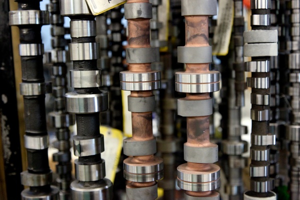
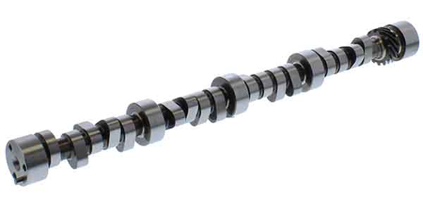
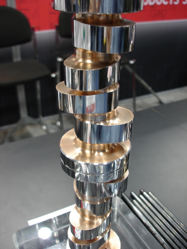
Photo courtesy of Camcraft Cams.
Contemplate on Your Calculations
Comparing one cam grind to another can be tricky because camshaft suppliers often measure their cam specifications differently.
If duration is measured at .004˝ of lift rather than .050˝ of lift, it inflates the numbers and makes the cam appear bigger.
Consequently, it’s important to note at what point lift is actually measured when comparing advertised camshaft duration specs.
Generally speaking, the longer the duration the higher the rpm range where the cam makes power. Short duration cams are good for low speed torque and throttle response while long duration cams are best or high revving engines that need to make lots of top end power.
Cams with durations in the 195 to 210 degree range (measured at .050˝ cam lift) are usually considered best for stock unmodified engines and those with computerized engine controls.
Once you go beyond 210 to 220 degrees of duration, intake vacuum starts to drop. This upsets idle quality and affects the operation of computerized engine control systems.
Performance cams typically have durations ranging from 220 up to 280 degrees or more. The longer the duration, the rougher the idle and the higher the cam’s power range on the rpm scale. A cam with a duration of 240 degrees of higher will typically produce the most power from 3,500 to 7,000 rpm.
But there’s more to camshaft selection than lift and duration. Cams from two different manufacturers may have identical lift and duration specs, but have considerably different performance characteristics because of the shape of the lobes.
A lot of development work has gone into revamping lobe profiles in recent years to optimize performance, and many cam suppliers have introduced new product lines that reflect these improvements.
Some cam lobes may have steeper or shallower ramps to change the
velocity at which the valves open and close. A fast opening rate is great as long as the valve springs and valvetrain are stiff enough to handle it. Closing the valves quickly is also good, but not good if the valves close so abruptly that they bounce when they hit their seats or the lifters can follow the down ramp of the cam lobe.
Many cams today also have “asymmetrical” grinds that use different profiles for the upside and downside ramps on the cam lobes, as well as different lobes for the intake and exhaust valves.
Some cams even feature slightly different grinds for each of the engine’s cylinders, depending on where the cylinder is positioned in the engine block.
The end cylinders on a V8 with a single carburetor manifold typically benefit with a little more valve duration for the end cylinders to equalize airflow through the intake manifold. It’s a trick that NASCAR has used for years and is now available in some off-the-shelf product lines.
Down the Road
What type of changes or technology improvements will engine builders see in their cam selection coming down the road? “One of the newer developments has been the use of tool steel for roller camshaft cores,” explained one manufacturer. “These high-strength cores allow a larger gun drill through the camshaft, which reduces the rotating mass, decreasing parasitic losses in power output.”
Also, the trend to increasingly larger cam bearing diameters and the resulting increase in base circle diameter is allowing for larger lobes and greater lobe lift which reduce the rocker arm ratios and valve spring pressures required for controlling the valve train.
Here’s a list of common mistakes we have determined to cause camshaft failure:
Reasons for Cam Failure
1. Lobe Wear
Use only the manufacturer recommended lubricant, which is generally included with the cam. This lubricant must be applied to every cam lobe surface, and to the bottom of every lifter face of all flat tappet cams. Roller tappet cams only require engine oil to be applied to the lifters and cam. Also, apply the lubricant to the distributor drive gears on the cam and distributor.
2. Incorrect Break-In Procedure
After the correct break-in lubricant is applied to the cam and lifters, fill the crankcase with fresh, non-synthetic oil. Prime the oil system with a priming tool and an electric drill so that all oil passages and the oil filter are full. Preset the ignition timing and prime the fuel system. Fill the cooling system. Start the engine. The engine should start quickly and run between 1,500 and 3,000 rpm.
If the engine will not start, don’t continue to crank for long periods as this can shorten the life of the cam. Check for the cause of the problem and correct it. The engine should start quickly and be run between 1,500 to 3,000 rpm. Vary the rpm up and down in this rpm range for 20 minutes. During break-in, verify that the pushrods are rotating, as this will show that the lifters are also rotating. If the lifters don’t rotate, the cam lobe and lifter will fail. Sometimes you may need to help spin the pushrod to start the rotation process.
3. Always Use New Lifters With A Flat Tappet Cam
If you are removing a good used flat tappet cam and lifters and are planning to use them again in the same (or another) engine, you must keep the lifters in the order they were removed from the cam they were on. Lifters “mate” to their specific lobes and can’t be changed. If the used lifters get mixed up, discard them, install a new set of lifters, and break in the cam in again. You can use new lifters on a good used cam, but never use used lifters on a new cam.
4. Incorrect Valve Spring Pressure
Recommended valve spring seat pressure for most street-type flat tappet cams is between 85-105 lbs. More radical street and race applications may use valve spring seat pressure between 105-130 lbs. For street hydraulic roller cams, seat pressure should range from 105-140 lbs. Mechanical street roller cams should not exceed 150 lbs. Race roller cams with high valve lift and spring pressure are not recommended for street use, because of a lack of oil splash onto the cam at low speed running. Springs must be assembled to the manufacturer’s recommended height. Never install springs without verifying the correct assembled height and pressures.
NOTE: Increased spring pressure from a spring change and/or increased valve lift can hinder lifter rotation during cam break-in. Decreasing spring pressure during break-in can be accomplished by using a shorter ratio rocker arm to lower the valve lift and/or removing the inner spring if dual springs are being used.
5. Mechanical Interference
A. Spring coil bind. This is when all of the coils of the spring contact each other before the valve fully lifts. Valve springs should be capable of traveling at least .060″ more than the valve lift of the cam from its assembled height.
B. Retainer to seal/valve guide boss interference. At least .060″ clearance is required between the bottom of the retainer and the seal or the top of the valve guide when the valve is at full lift.
C. Valve to piston interference. This occurs when a change in cam specs (lift, duration, or centerline) is enough to cause the valve and piston to contact. Also, increased valve size or surfacing the block and/or cylinder head may cause this problem. Minimum recommended clearances are .080″ intake and .100″ exhaust.
D. Rocker arm slot to stud interference. As you increase valve lift, the rocker arm swings farther on its axis. Therefore, the slot in the bottom of the rocker arm may run out of travel and the end of the slot will contact the stud and stop movement. The slot in the rocker arm must be able to travel at least .060″ more than the full lift of the valve.
6. Distributor Gear Wear
The main cause for distributor gear wear is the use of high volume or high pressure oil pumps. If these types of oil pumps are used, reduced cam and distributor gear life will result. However, you can increase the gear life by adding more oil flow over the gear area to help cool off the point of contact.
7. Camshaft End Play
Some engines use a thrust plate to control the forward and backward movement of the camshaft in the block. The recommended amount of end play on these types of engines is between .003″ to .008″. Many factors can cause end play to change. When installing a new cam, timing gears, or thrust plates, be sure to verify end play after the cam bolts are torqued to factory specs. If the end play is excessive, it will cause the cam to move back in the block, causing the side of the lobe to contact an adjacent lifter.
8. Broken Dowel Pins or Keys
The dowel pin or Woodruff key does not drive the cam; the torque of the timing gear bolts against the front of the cam does. Reasons for the dowel pin or key failing are: Bolts not being torqued to correct specs, incorrect bolts of a lower grade stretching and losing torque, not using the correct hardened washer which may distort and cause torque of the bolt to change, LocTite not being used, or some interference with the cam, lifters, or connecting rods causing the cam to stop rotation.
9. Broken Cam
A broken camshaft is usually caused by a connecting rod or other rotating part coming loose and striking it. Sometimes the cam will break after a short time of use because of a crack or fracture in the cam due to rough handling during shipping or improper handling prior to installation.