 As you’ll recall from previous issues of Engine Builder we hoped to take a piece of American Iron history and use technology options from modern day to bring the old pieces up to speed with the new. This engine was built with specific parts for a specific purpose, but other aftermarket parts can be used to create your own custom version of this engine for your customers’ needs.
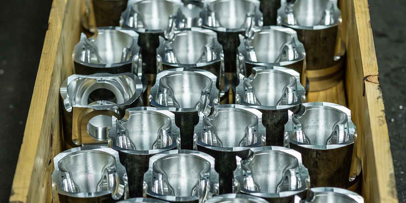
Because there are so many aftermarket options for these FE engines, the main, original piece we ended up using was the block. With such a build, it can become quite comical because, if you’re a true gear head, you feel just like a kid in a candy store – you tend to want some of everything.
I will admit that this project was a real experience, and at times proved to be something of a monumental task. Through the building process of our FE engine project, we did encounter a few speed bumps in the road that we did not expect.
Sometimes it happens, even to the best of us. Even though you research and select the best parts for your build it doesn’t mean that it’s guaranteed to be easy. All of these parts have to come together like instruments in an orchestra to play their part.
The differences between expectation and reality can quickly become hilarious, because at the start of our build we simply wanted to do a good rebuild and make some power. By the time we finished, we were looking to go drag racing because we felt we had a Pro-Mod power plant. Making power becomes an addiction: a little is not good enough. Just like the kid in the candy store, you want all you can get. So even though we had totally blown out a budget build on this one, we were dying to get on the dyno to see the results.
But with our FE build almost complete, there were still a few things that we needed to iron out before we could dyno test the engine.
One speed bump that we had to iron out was the pushrods. The pushrod is a small component of the engine, but it plays a very important role. The PRW rocker arms we were using fit a variety of applications, so the first step was to correctly space the rocker arms in relation to the valve placement in the cylinder heads. Once the rocker arms were correctly shimmed and torqued on the cylinder heads, the correct length pushrod could be determined for proper rocker arm geometry. This length was determined by using two adjustable pushrods furnished in the rocker arm kit. Since the length was uncommon (9.25˝), we knew they would need to be custom made.
Pushrods are made for the engine application and the parameters under which it will operate. Factory pushrods for the FE had a 3/8˝ diameter and our new rocker arm set up also demanded a 3/8˝ diameter. To know exactly which type (correct material and thickness) of 3/8˝ diameter pushrod would work best in our operating range, we needed answers to some critical questions such as open spring pressure, cam profile, cylinder pressure, and rocker ratio. With our combination, we had an open spring pressure of 597 lbs., a 1.75:1 rocker ratio, and with our cam profile we determined that one of the Series 5 pushrods from Manton would fit the bill. Our Series 5 custom pushrod would be made with 4130 chromoly tubing 9.25˝ long with a wall thickness of .140˝. The Series 5 pushrod is for high performance use for non-guide plate applications.
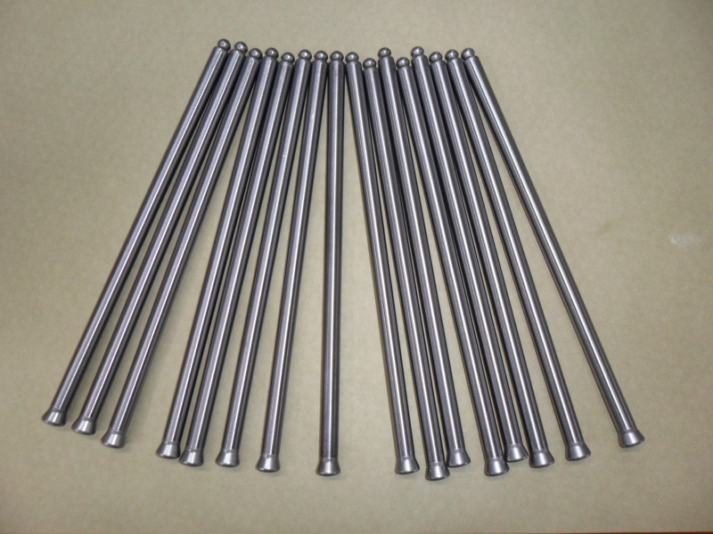
performance use without guideplates. The diameter was same as stock being 3/8” but had a wall thickness of .140”.
After receiving the pushrods and installing them, one thing we realized is that the top of the pushrod holes in the head had to be chamfered. When trying to set the valve lash, the pushrod was barely touching the top of the pushrod hole. So we machined the tops of the pushrod holes to eliminate the scrub and properly set the valve lash.
We had originally determined that our engine would be fuel injected with a FAST multi-point system, but we wanted to establish a few parameters that could be used as inputs to our EZ-EFI. We intended to dyno the engine two ways: first, we wanted to break the engine in and fine-tune it with a carburetor. Then, we would convert the engine over to fuel injection and compare power differences. I thought this would be a great opportunity for a real-world comparison. Most of the time when you have an engine on the dyno, you’re optimizing it for the customer’s demands. If they want a carburetor, you optimize the engine with the carburetor. When there is fuel injection, you tune the fuel injection. You don’t usually have too many opportunities to dyno both systems on the same engine.
Of course, in order to dyno test both systems we had to outfit the engine for both configurations while the engine was on the stand so that dyno testing would be much easier.
An FE engine is a different breed from other Fords, with a different bell housing bolt pattern and motor mount configuration. Darryl Diamond of Diamond Research in Bethlehem, N.C. has experience dyno testing FE engines and since he already had the necessary pieces to fit the engine to his Superflow dyno, we used his facility. Darryl’s shop is a complete in-house engine machining and test facility founded in 1982 by his father Jesse along with his brother Chris. They owned their own racing team and ventured into various racing series such as NASCAR Nationwide, Late Model Stock, Goody’s Dash Series and Pro-Cup. In 1987, they expanded their operation and started building competitive racing engines for the public while racing their own team. In 2004, their father Jesse passed away unexpectedly and in 2005, they closed the car shop and concentrated on their engine program. To this day, their engines have powered over 300 wins.
With the help of Darryl’s employee Tracy, the engine was loaded in the dyno cell and ready for testing. For our initial testing, we choose a 650 CFM HP series Holley carb that was fully adjustable with changeable idle and high-speed bleeds. The first reaction that you probably have is “that carburetor is too small!” Rest easy – this carburetor was Darryl’s and had been fine tuned in a previous test session at his facility with a similar cubic inch engine. It would be a great starting point for our comparisons.
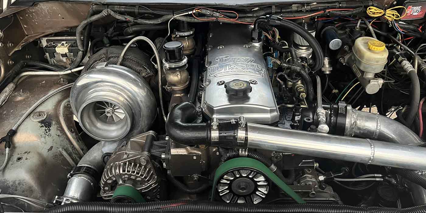
 The ignition system for the carburetor test session was an HEI distributor out of a later model FE engine. With this distributor we could also use the socket style plug wires from our original engine. We used the wiring harness for the pick-up coil of the distributor to trigger the MSD box mounted in the dyno cell. The ignition coil used was from ICE ignition systems and was mounted on the front of the driver’s side cylinder head. For the fuel injection testing we would use a dual sync distributor from FAST. The dual sync distributor is basically a cam and crank sensor for the fuel injection system. The crank sensor triggers the MSD box to control ignition while the cam sensor is used as reference to fire the injectors. The EZ-EFI system is available with the option for the ECU to control ignition timing. We wanted to utilize this function and use our timing curve from the carburetor testing and input these parameters into the FAST system. While the engine was on the engine stand the dual sync distributor was installed and a custom set of plug wires were made and placed in a wire loom that bolted to the valve covers. Then we removed the distributor and neatly placed the custom made plug wires out of the way so we could install our HEI distributor back in the block for the carburetor testing. At the rear of the passenger side head, an aluminum plate was made to hold the ECU for the fuel injection and also an air fuel ratio meter to be used during the carburetor testing. The information that we obtain from the air fuel ratio meter could also be used as inputs for the FAST fuel injection system.
So with the engine loaded on the dyno and set up for both kinds of testing, we were ready to fire. It is at this point in every engine build where I start feeling as though I’ve reached a crossroad. On one hand I’m happy because we’ve finally made it and I’m anxious to see the payoff in the end. On the other hand, in the back of my mind is Murphy’s Law: “what can go wrong, will go wrong.” In this case, Murphy was wrong.
With a push of the “start” button, the engine fired up flawlessly. We brought the engine speed up to around 2,000 RPM and watched closely as the engine began its break-in. We used AMSOIL Break-In oil and wanted to get the engine up to operating temperature and then shut it down and let it cool. This gave the valve springs a chance to break-in with a good heat cycle and, while the engine was cooling, gave us a chance to check the valve lash on our solid roller.
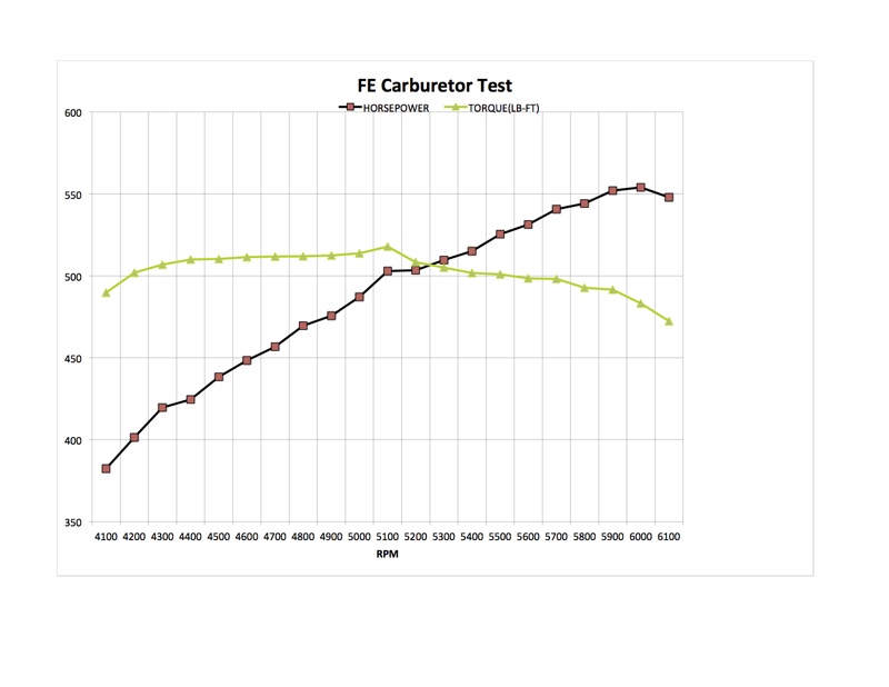
After the engine cooled, we fired it back up and checked over everything along with our ignition timing which we started out at 30° total. Our first pull we took the engine to 5,000 RPM while watching the air fuel ratio to see how the jetting of the carburetor would pan out. For the first pull, the air fuel ratio was great ranging between 12.5:1 and 12.7:1. We continued to make several more repeated pulls and the engine would keep squeaking a little more power with each pull. With the engine broken in we increased the engine speed to 6,000 RPM. At this point, the engine was making 513 horsepower at 6,000 RPM. So, we increased the total ignition timing to 32°. On the next pull, the engine gained almost 20 horsepower making 531 horsepower. We advanced the ignition timing again to 34° and to our surprise, this time the engine made 547 horsepower. At this time, we were all surprised so we brought the ignition timing to a total of 35°. This time the engine made 555 horsepower at 6,000 RPM and 517 lb. ft. of torque at 5,100 RPM. The 35° of total timing is what the engine liked and we had tailored the timing curve on the lower RPM range. The amazing thing was that the torque was 501 lb. ft. at 4,000 RPM. The torque curve of the engine was almost flat having 500 lb. ft. in an RPM range from 4,000 to 5,400.
I have to admit we were very happy. We had 431 cubic inches with 10.8:1 compression and would have been happy if the engine made 500 horsepower on pump gas. But, 555 horsepower on pump gas in an FE Ford package? We were ecstatic! Now we wanted to see if there were any differences so we converted to fuel injection. With the throttle body of the fuel injection system capable of 1200 cfm, we again worried that our 650 carburetor might have been too small for our testing. But there comes a point where big is not always best. There is a point of diminishing returns where the engine is only going to get the amount of air that it can take in. Would CFM differences shed some light? We would soon find out.
After installing the distributor and the fuel injection components we could test our fuel injection system. The oil was changed to AMSOIL 10W30 racing oil and the valves were re-adjusted. When the battery power was hooked up to the FAST system, we answered the preliminary questions on the handheld touch screen and supplied our inputs for the air fuel ratio and timing curve settings. The fuel system used was also part of the EZ-EFI system. After checking fuel pressure and making some adjustments, the engine was again ready for testing.
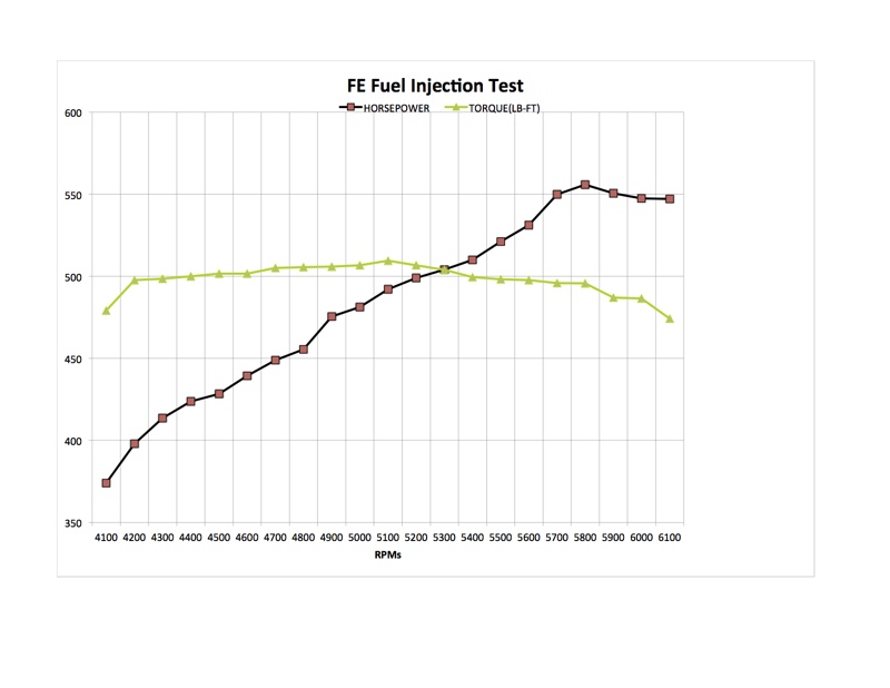
When the “start” button on the dyno was pressed, the engine cranked and ran flawlessly. While monitoring the dash of the handheld, we could see the ECU learning and correcting and the engine was operating within the parameters that were specified. This turned out to be an easy and simple transition into a fuel injection system. The plan was to make three moderate pulls on the engine, make sure that the ECU was learning with each pull. After each, we would cut the engine off and power down the ECU then power it back up again and continue to make some more moderate pulls. The way this system is designed to work, the ECU can only correct up to 25% of the air fuel ratio in either direction (being rich or lean) with each ignition cycle. So, by letting the engine run then shutting it down and then turning it back on, the ECU could correct again an additional 25% than started previously to achieve its target air fuel ratio. The surprise came when, after three pulls, the engine was making close to the same power as the carburetor. When starting the engine for the fourth pull, we ran the engine up to 6,200 RPM and the dyno readings were almost identical to what the carburetor had produced. We continued to run the engine for several more pulls and the results remained exactly the same. On the eighth pull, the power and torque started to decrease slightly. The engine seemed fine so three more pulls were made and the results showed more of a decrease in power. At this time, we cut the engine off and let the dyno cell fans run to cool the engine off and drop temperature in the room. After about 25 minutes, the engine was fired back up – the power and torque were back up again. We continued to make three more pulls and the engine held steady, but on the fourth pull the power again started dropping back off.

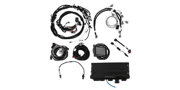
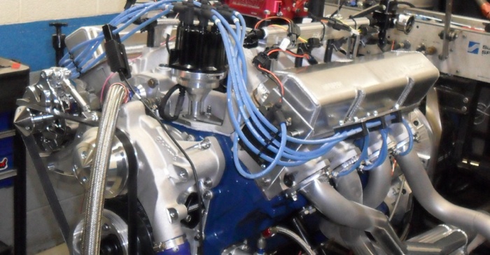
engine was converted to fuel
injection. On the backside of the
passenger cylinder head you can see our ECU and wiring harness along with the dash board of the EFI system.
For years, top engine builders seem to always prefer a carburetor over fuel injection and my question has always been why. Fuel injection is recognized for its precise tuning capabilities, so why is the carburetor still used in a lot of racing classes where fuel injection is permitted? This comparison shed some light on the reasoning.
The cooling effect of the carburetor is always worth more consistent power because it helps drop the intake manifold temperature. As we found with the multi-port fuel injection system, when the temperature rises in the intake manifold there is no cooling effect from the fuel and the power begins to descend. This fact can be very important to a racer. On the other hand, how many street rodders dyno their engine and fine-tune their carburetor? Carburetors that are not fine-tuned can be a nightmare to the daily driver and weekend hotrodder. A good scenario for this situation would be to install a fuel injection system with the injectors installed in the throttle body. This way you could get the best of both worlds.
This FE engine build more than met our expectations. The build consisted of top brand quality parts that all proved very reliable. The engine had a total of 24 dyno pulls with our testing and not once gave us any issues due to our build. Anyone interested in turning a 390 FE into 431 cubic inches can easily find the parts and, with a little bit of work and creativity, can have 555 reliable and drivable horsepower for whatever situation they face.
While company names have been mentioned in this article for this particular build, we recognize that different products will yield different results in different situations: it’s the job of the engine builder to research parts and components that will yield the best results for YOUR build.
If you missed any of the previous installments in this quest to bring a vintage engine up-to-date with some modern technology, you can read articles in the April and October 2014 issues.
Additional enhancements to this article are available on our website at www.EngineBuilderMag.com. For contact information, use our online Buyers Guide at the same location.