 From the persistence and determination of Rudolf Diesel evolved the greatest invention for the transportation industry, the diesel engine. Who could have ever imagined that so many different manufacturers of these engines would have evolved from one design? I guess the same could also be said for the gasoline engine as well, but, regardless of the manufacturer, have you ever stopped to think how much the diesel engine has evolved?
First, it was the quest for more power, then the focus went to power with efficiency, and now power, efficiency and emissions are all required. Emissions has almost become a subject we’re already tired of hearing about, but the manufacturers go through numerous trials to keep their engines compliant with government “clean air” standards.
Especially in a Class 8 truck, it’s interesting to see changes that have taken place that can be hidden in plain sight.
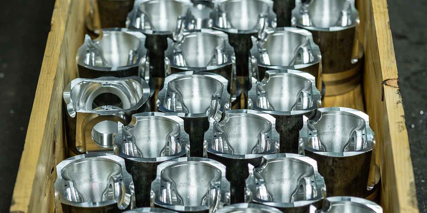
engine weighs approximately 2560 lb. dry. Its design includes a one-piece cylinder head, a single overhead camshaft, three rocker arms per cylinder, unit injectors and no pushrods. Monosteel steel pistons are made in one piece.
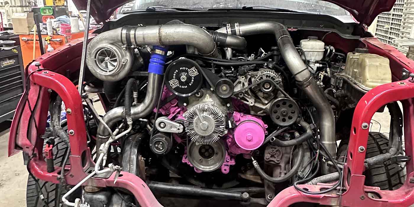
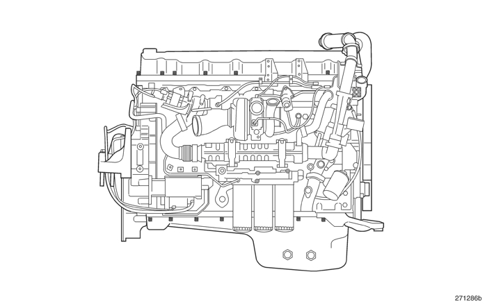
The Mack MP8 13-liter engine (and its Volvo counterpart, the D13) at first glance seems to be very similar to any other modern day diesel power plant. It uses the standard emissions devices including the EGR system, DOC (Diesel Oxidation Catalyst), DPF (Diesel Particulate Filter), electronic injection and VGT (Variable Geometric Turbo). But, behind the scenes are some interesting details that make the engine unique. From colors of the engine and appearance of the valve cover along with labels and filters, several features distinguish the MP8 from other engines even within the Mack line.
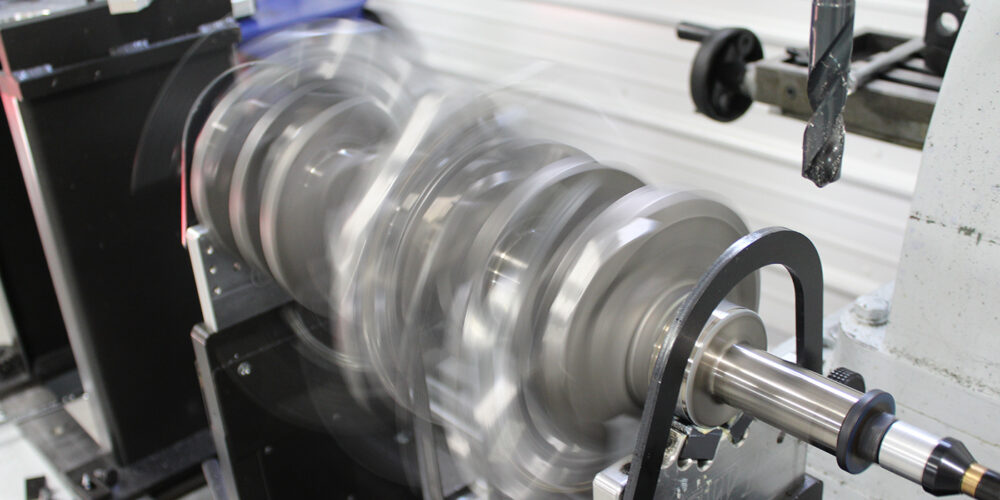
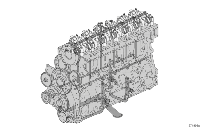
On the front of the engine there are two poly V belts that drive the accessories. The outer belt drives the coolant pump and fan hub. The second belt drives the alternator and A/C compressor. This is no different than other diesel engines except for the fact that behind the accessories on the front of the engine there is no gear train. On most diesel engines, behind the belts there is a front cover, which houses the engine’s gear train linking the crankshaft, camshaft and accessory drives. On the Mack, the gear train has been moved to the rear of the engine. This was done to improve the flow of cooling air around the front of the engine. On the back of the engine the timing gears are backed by a ¼” steel plate that is bolted to the block. There are nine gears total, which help make timing more precise along with reduction in noise levels.
The cylinder block is cast iron just as is the case with other diesel engines; but for more rigidity and noise and vibration reduction, a stiffener plate was added to the bottom. When removing the oil pan you can see the stiffener plate and when removing the stiffener plate the main bearing caps are exposed.
There are seven main caps made of nodular cast iron. Each cap is marked for its specific location starting with No. 1 at the front.
Main caps No. 4 and No. 7 are not marked and have a specific purpose. Main cap No. 4 houses the thrust washers to control axial movement of the crankshaft and main cap No. 7 is the attaching point at the rear of the block for the oil pump.
The connecting rods are forged steel and made by “fracture” process with four M12 capscrews. The pistons are one-piece Monosteel.
 The Mack MP8 also has a somewhat complex lubrication system. Its system components are similar to other manufacturers, but the functions of the lubrication system are often overlooked and may not be fully understood as to what takes place inside the engine. The oil pump is mounted to the rear main bearing cap No. 7 and is gear-driven by the crankshaft. Oil flows through the pump into three filters, two of which are full-flow and the other a by-pass. Once oil passes through the filters, six valves control oil flow through the lubrication system. The six valves are:
1. Reducing Valve – Maintains constant system oil pressure;
2. Safety Valve – Prevents excessive pressure during periods of high viscosity;
3. Oil Cooler Thermostat Valve – Prevents oil from entering the oil cooler until warmed to a set point;
4. Overflow Valve: Full-Flow Filter – Allows oil to by-pass filter if it becomes clogged;
5. Opening Valve: Piston Cooling – Prevents oil from moving to the piston cooling jets until the system reaches set pressure;
6. Control Valve: Piston Cooling – Regulates oil flow to the piston cooling channels.
features a strainer and pickup tube that lead the lubricant into the pump. For the axle forward oil pan, the strainer is mounted on a short tube held in place by a bracket attached to the distribution housing. For the axle back model, a long tube without the bracket is supplied.
One unique feature of the Mack MP8 lubrication system is its CCV (Crankcase Ventilation) system. Though the CCV system has become a standard emission system on all makes of engines to prevent crankcase vapors from escaping to the atmosphere, most diesel engines today have a tube from the valve cover that carries the crankcase vapors to a filter housing. The filter captures the oil mist from the vapor and traps it in a filter that is serviced about every 100,000 miles. The vapor is then reintroduced into the intake tract where the vapor can be returned to the engine to be re-burned.
For the Mack MP8, the CCV system consists of a turbine separator. The mixture of oily mist and gases trapped in the valve cover and timing cover drain onto the top of the center of a turbine and run down onto several discs rotating within the turbine. Separation occurs as the mixture is flung outward by the turbine and strikes the walls of the CCV. The droplets of mist form into a liquid and drain back into the oil pan along with the oil that drives the turbine. The vapors are then free to exit through an open port that is at the bottom of the engine. As road draft passes the tube while driving, the vapors are drawn into the atmosphere.
Fuel system
Unlike most emissionized diesels today, the Mack MP8 engine does not utilize a common rail injection system. Most diesel engines use common rail injection as a way to control many fueling strategies for a better and more efficient burn and to bring down emissions – but it is very complex and still prone to many problems. The Mack MP8 utilizes what is known as unit injectors. Unlike common rail systems that have separate components for delivering, pressurizing and injecting the fuel, the unit injector combines all of these functions.
The unit injector uses a double solenoid known as pump and nozzle and is located in the same housing of the injector. The unit injector is held in the cylinder head by a yoke, which attaches to the cylinder head with a bolt. Depending on mode year, one of three different styles of yokes were used. So, if you are servicing the injector, it is recommended that the yoke hold down bolt be replaced. Make sure what yoke is on the engine and get the proper length replacement.
The fuel pump attaches to the power steering pump, which is turned by the rear gear train of the engine. The fuel is filtered both before entering the pump and when leaving it. At 600 rpm, the pump delivers 14.5 psi of pressure and at 1200 rpm around 43.5 psi. Fuel enters the head and is delivered to all six injectors.
 There are four phases of the injector cycle of operation. First is known as the Fill phase. Inside the top of the injector is a plunger. The plunger is pushed down by the rocker arm, which is moved by the lobe on the camshaft. The plunger moves up in the injector as the camshaft rotates and the rocker arm is on its way to the camshaft base circle, the fuel valve is open allowing fuel to be drawn in. Filling continues until the pump plunger reaches its upper position.
Next the spill phase begins. As the camshaft rotates, the rocker arm pushes the pump plunger down. Fuel flows through a fuel valve through holes in the injector and into the fuel gallery.
Then begins the injection phase. As the rocker arm continues to push down on the plunger, the fuel valve closes and injection occurs allowing fuel to exit the nozzle. The injection phase ends when the fuel valve opens and pressure inside the injector drops below nozzle opening pressure.
Finally comes the pressure drop phase. The fuel valve opening and closing is controlled by the double solenoid, which is electronically actuated by the ECM (Engine Control Module).
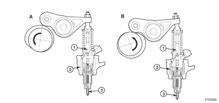
Fill phase, Spill phase, Injection phase, and Pressure drop phase.
Within each of these four phases, the pump plunger (1), fuel gallery (2) and injector nozzle (3) work together to pump fuel through the engine.
The fuel valve opening and closing determines the amount of fuel per injection stroke. Each injector is labeled with a trim code. When the injector is replaced, the new trim code has to be programmed into the ECM for the cylinder it is replacing for proper fuel management. Copper sleeves are in the injector bores of the cylinder head. Engine coolant circulates around the copper sleeves to act as cooling jackets to control injection temperature.
Important things to remember when servicing the engine include not machining the cylinder head for simple clean up. This will change injector depth and affect emissions. This will also upset the timing gear backlash in the rear gear train. Also, do not grind the injector copper sleeves.
When removing the main caps of the crankshaft, make sure that they are installed back in the correct position. The same thing applies with the rod caps as they are fracture manufactured.
When removing and installing the cylinder head, make sure to use the alignment screws and washers on the side of the head and block to maneuver the head while lowering it back onto the cylinder block. Because the head gasket has elastomer sealing rings, if the head is lowered onto the gasket and then slid into place, damage to the gasket may occur and result in improper sealing.
 Each cylinder has four lobes of the camshaft that operate it. Make sure that the rocker assembly is kept in the order from the engine in which it is removed.