This is a great article for understanding the basics of fuel pressure regulator function. The article can be found at http://fuelab.com/forums/forum/customer-support-2/pressure-regulators/ within the “Bypass or Return Style Regulators” and “Blocking or Traditional Style Regulators” sections. This article expands on the earlier articles with focus on “Boost Reference”.
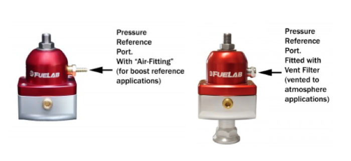
Let’s start by identifying the Pressure Reference Port of a fuel pressure regulator. This is the small “air fitting” on the side of the regulator cover. Or with some carbureted regulators, it may be a small hole in the side or rear of the regulator cover. The Pressure Reference Port provides a point of reference for fuel pressure control. With forced induction systems (turbocharging and supercharging), this port is used to receive a “boost reference” to increase fuel pressure under boost conditions. The boost reference originates at the induction system of an engine, and acts upon the diaphragm in the regulator, thereby enabling the regulator to compensate for boost pressure. If the port is not used to maintain constant fuel pressure, such as with normally aspirated engines, then it is vented to the atmosphere. With the atmosphere as a reference, the fuel pressure is constant with atmospheric pressure. In this case it is important to not plug up the pressure reference ports or holes in the regulator, as slight pressure errors can occur.


To describe how “boost reference” works, let’s first describe how the diaphragm of a fuel pressure regulator functions to control fuel pressure. Please note, the description below describes the diaphragm/fuel control valve operation of a blocking style regulator – it provides an example of general diaphragm function. More detailed explanation of the function of the components described below is covered in the earlier articles.
The fuel pump delivers fuel from the tank to the regulator, which is then distributed to the carburetor. Fuel line pressure is high from the fuel pump to the regulator, and then less from the regulator to the carburetor, or fuel rail. As fuel pressure in the carburetor float bowls increases, so does pressure within the regulator, causing fuel to push upward against the diaphragm. As fuel pressure increases, the diaphragm moves upward, and the fuel control valve progressively reduces fuel flow and pressure as it is moved toward a closed position. When the fuel pressure reaches the maximum pressure to which the regulator has been set (this pressure setting is usually based on the maximum which the carburetor manufacturer has specified will provide optimal performance), the diaphragm has pushed upward to where it has closed the fuel control valve. As the engine demands fuel, the float bowls begin to empty and this causes fuel line pressure to drop. As line pressure drops the regulator diaphragm descends, which progressively opens the fuel control valve, increasing fuel flow and line pressure.
With turbocharged or supercharged applications, boost reference must come into play. Take the example of a carbureted application utilizing a blow-through forced induction set-up. When under boost, compressed air from the turbo (or supercharger) is blown through the carburetor, which pressurizes the carburetor and the float chambers. Fuel being fed to the carburetor will encounter resistance from this pressurization. For example, let’s say a carburetor requires 8 psi of fuel pressure and the engine is currently being delivered 7 psi of boost pressure. The carburetor is now under 7 psi of boost pressure which is resisting the 8 psi of fuel pressure being delivered from the regulator. That means 7 psi of the fuel pressure delivered to the carburetor must be used to overcome resistance, netting only 1 psi being delivered to the carburetor. This can allow the float chambers to run dry, and interrupt fuel flow to the engine. In order for the carburetor to deliver 8 psi to the engine, the regulator needs to provide an additional 7 psi to overcome resistance. That means a total of 15 psi of fuel line pressure must be allowed by the regulator. However, the diaphragm has been set to move the fuel control valve to the closed position once line pressure of 8 psi has been reached. Boost reference must be used to so the regulator can compensate for this. A boost reference line (tube, or hose) is run from the carburetor box, or hat, to the Pressure Reference Port. As boost pressurizes the carburetor, the same amount of pressure is applied to the boost reference line, which pressurizes the diaphragm housing of the regulator. This pressure is applied to the top side of the diaphragm so that it becomes more difficult for fuel line pressure to move it upward. Thus working together with the diaphragm spring to allow more fuel pressure (8 psi spring + 7 psi assistance = 15 psi). Boost reference enables fuel pressure to be raised 1:1 with boost pressure – overcoming the rising air pressure and making certain the float chambers remain properly filled. WITH ALL ELSE BEING EQUAL, for every amount of pressure change that occurs at the Pressure Reference Port, an equal change in fuel pressure will result.
The same principal applies to boosted EFI applications; the regulator needs to allow additional fuel pressure to overcome resistance created by boost pressure. For example, let’s say a boosted application runs 45 psi of fuel pressure to the injector when under no boost. Let’s say the engine is then put under 20 psi of boost pressure. That means the intake manifold, where the fuel injectors are mounted and spray into, is pressurized by 20 psi. This pressure then “pushes back” fuel in the injector/fuel rail by 20 psi. That means the fuel pressure in the fuel rail must be increased by 20 psi to compensate. So, the 20 psi of boost reference to the Pressure Reference Port causes the regulator to increase fuel pressure in the fuel rail/delivered to the injector from 45 psi to 65 psi – thereby compensating for the 20 psi of resistance created by boost pressure.
However, it should be noted various conditions can affect regulated pressure readings. While Bypass (Return) Style or Blocking (Traditional) Style regulators that use diaphragms are exactly 1:1, in some situations when measurements are taken, it appears less than 1:1. For example, some with Bypass Style regulators have measured their fuel pressure and boost pressure for a blown application and found it to be less than 1:1. For many of these users, they are comparing the operating conditions between idle and full throttle. During full throttle operation, much less fuel is returning back to the fuel tank than during idle operation. When the regulator is returning less fuel, the diaphragm is “more closed” and therefore in a slightly different position, such that the amount of squeeze on the diaphragm spring is less. With less force from the spring, the pressure lowers. The amount of pressure change as a result of how much flow difference is going through the valve is known as the Regulation Slope. Regulation Slope represents the amount of pressure difference (PSI) expected per change in flow rate (GPM). For example, say an engine consumes 1 GPM (60 GPH) at full throttle and the regulator has a Regulation Slope of 3 PSI/GPM, then we can expect that the fuel pressure will lower by 3 PSI at full throttle compared to when measured at idle.
Source: FUELAB