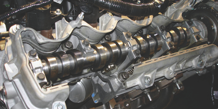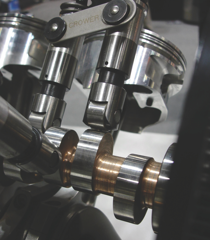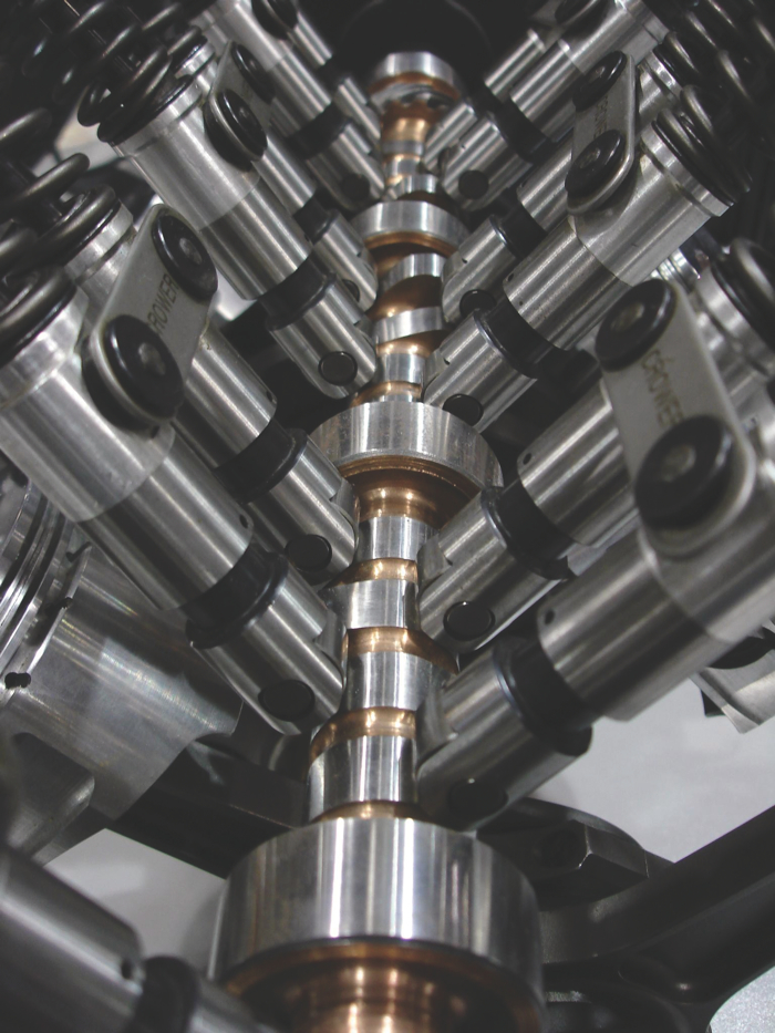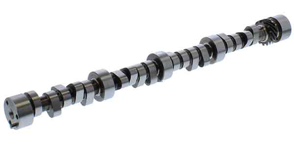
If you’ll recall, in the January issue, we got into the nitty gritty details of what makes a camshaft the “right” camshaft. In this issue, we’ll continue the education. Cam class is back in session!
Remember the camshaft makes one complete revolution (360°) while the crankshaft rotates twice (720°) for a complete engine cycle. Camshaft timing is usually expressed in crankshaft degrees relative to piston location in the cylinder, corresponding to TDC and BDC. This means that the four piston strokes that occur during 720° of crankshaft rotation position the piston at both TDC and BDC twice.
Before we decide to change the opening or closing point of a lobe, either via adding duration or advancing a lobe, understand the effect is also occurring on the other side of lobe proportionately. As with most decisions on an engine build, a harmony must exist between all parameters. If we modify one valve timing event the possibility exists that a sequence of repercussions could notably affect engine performance positively or negatively.
Valve timing events can be tailored in several ways. Option one is duration can be added or subtracted. If duration is added to the lobe the valve is opened and closed later. Conversely, removing duration delivers inverse results.
The other method is advancing or retarding the camshaft. Advancing the cam lobe opens and closes the valve earlier while retarding the lobe produces the opposite occurrence. Adding duration and moving the lobe in one direction or the other preserves the original opening or closing at the same time applying the added duration on the opposite ramp of the lobe. Performing any of the possibilities listed carries ramifications that may be beneficial or conflicting.
Cam Timing Relationship
• If the camshaft is retarded – Better high RPM breathing but an unstable idle and reduced power at low RPM
• If the camshaft is advanced – More stable idle and good low-RPM power, but poor breathing and low power at high RPM
The Timing Events
The valve timing events occur in this order of importance (well, this is debatable, somewhat).
1. Intake valve closing (IVC)
2. Intake valve opening (IVO)
3. Exhaust valve closing (EVC)
4. Exhaust valve opening (EVO)
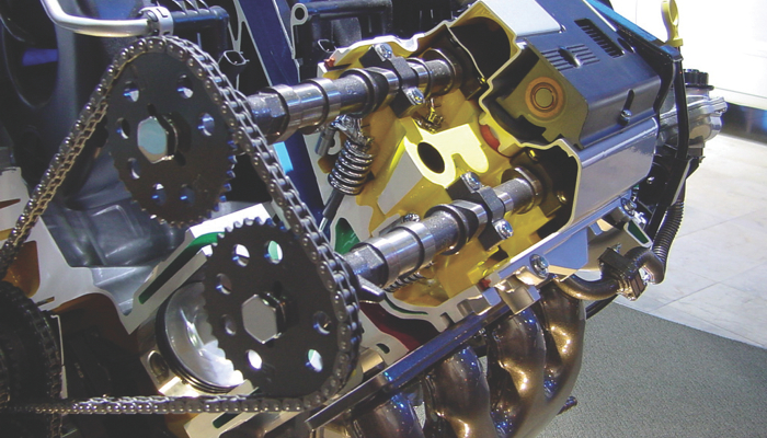
The Intake Lobe
You will notice that the intake valve events are placed in the first two positions of importance. Intake events tend to be less forgiving to change than exhaust events. Even small changes in engine design can have serious effects. Considerable debate does exist as to which event (IVO or IVC) is the fundamental aspect of power generation. For purposes of this article we will use IVC as the most critical.
Duration of the intake lobe design is critical for building power. Increased duration allows more of the air charge to fill the cylinder extremely critical at high RPM. To make use of the added duration an increase in RPM is also necessary. Cylinders hold an equal volume of air regardless of RPM.
Example: an engine at 650 horsepower uses approximately the same amount of air charge as it does at idle. As RPM increases a corresponding reduction in valve open time occurs. The valve is open for the same amount of degrees, but time opened diminishes as RPM is increased. All engines will eventually “tap out” as mechanical movement becomes too fast for airflow to fill the cylinder. By simply increasing duration (milliseconds), time is added to help fill the cylinder efficiently.
As duration is added, the opening and closing point of the valve are extended. This benefits breathing by placing the valve at a higher more useful lift as the induction stroke begins. Extending the duration also increases the responsiveness of the air/fuel mixture to piston location. At high RPM inertia of the air charge continues to fill the cylinder ABDC as the piston begins to ascend in the bore.
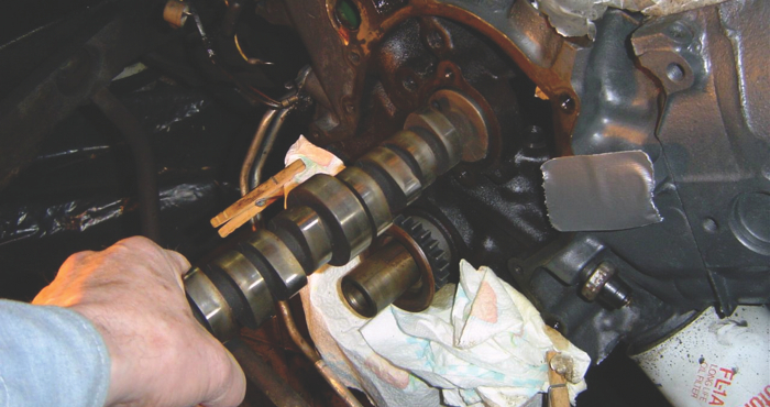
Intake Valve Airflow
This is based on time in milliseconds and is critical to producing power. Let’s look at how air actually flows through a naturally aspirated engine and why the proper camshaft can aid in cylinder fill for a chosen RPM range. Crankpin angle is critical because the air entering the cylinder doesn’t achieve maximum velocity until the crankpin approaches 45° after top dead center (ATDC). Most of the air flow into the cylinder should therefore occur somewhere between 45° and 135° ATDC.
To calculate the duration of any intake valve timing event, add 180° to the intake opening and closing time. For example, if an intake valve opens at 12° before top dead center (BTDC) and closes at 40° after bottom dead center (ABDC), the duration of the valve timing event is 232°. Exhaust timing follows a similar calculation.
The column of air contained within the intake port and manifold runner has inertia, which means that it tends to remain at rest or remain in motion. The column of air contained within an intake port must also constantly accelerate and decelerate in relation to the opening and closing of the intake valve.
As piston speed increases less time is available for the cylinder to fill completely before the piston reaches BDC limiting RPM and proper engine breathing. Opening the intake valve slightly before the piston reaches TDC can increase high-speed volumetric efficiency. Rapid piston movement creates both a faster moving air charge and pressure differential in the cylinder. The piston’s rapid movement nonetheless surpasses air charge velocity. At higher RPMs the initial intake charge is lagging prior to building speed after the opening of the valve. Once moving the charge gains speed and continues moving rapidly. Keeping the valve open longer ABDC uses the inertia of the fast moving charge to make up for the slow initial fill. Remember if airflow movement is fast enough we can pack more air into the cylinder with inertia than the piston could ever “pull” in by itself.
Inertia Charging
Charging is used to aid in cylinder filling at higher RPM. Closing the valve later, well after bottom dead center (ABDC), allows the benefits of high momentum airflow granting one last gulp of air as it pushes its way past the closing intake valve. The higher the RPM the later the intake valve closing should occur to ensure proper cylinder charge into the compression stroke. High RPM race engines benefit immensely from a continuation of airflow (inertia charging), into the cylinder as the intake valve is closing and the piston begins traveling upward on the compression stroke. This is due to piston speed increasing the velocity of the airflow(pressure wave), that is not easily impeded once in motion
By maximizing the kinetic energy of the air flow into the cylinders with the inertia supercharging effect, the volumetric efficiency is improved along with engine power. Similar to forced induction, inertia charging on a balanced engine build can increase VE over 100%. While high RPM use benefits from inertia charging, low-to-mid range RPM operation may decline as cylinder pressure is pushed back into the intake manifold.
Dynamic compression (DCR)
Dynamic compression is a mathematical equation derived from measured or calculated values that are actual dimensions of the engine including stroke, connecting rod length and intake valve closing. Dynamic compression rating is calculated by comparison of piston position in the bore to intake valve closing. This differs from static compression ratio (SCR) which is figured with piston at BDC.
Dynamic compression is always lower than static compression. Actual dynamic compression never changes notwithstanding the effect RPM has on cylinder pressure. Dynamic compression ratio should not be confused with cylinder pressure. Cylinder pressures change almost continuously due to many factors including RPM, intake manifold design, head port volume and efficiency, overlap, exhaust design, valve timing, throttle position, and a number of other factors. Therefore, unless variable cam timing is used, just like the static compression ratio, the DCR is fixed when the engine is built and never changes during the operation of the engine.
The Intake Valve Closing (IVC)
IVC is considered by many to be the most important timing event decision affecting both performance (peak torque) and/or economy. IVC is a major component of Volumetric Efficiency. The amount of the air/fuel charge is predominantly controlled by IVC. Intake valve closing regulates both effective compression ratio and RPM range by limiting the air/fuel mixture that enters the cylinder.
Maximum torque is delivered when the cylinder has the greatest mass of the fresh air/fuel charge that can be trapped. Harnessing the pressure waves that occur in the intake system generally aid in cylinder fill even after BDC is reached. Optimum IVC timing varies with engine RPM. As RPM increases the IVC timing deviates even more from BDC to harness the greatest result from the pressure waves.
Typically IVC is in range of 50° – 60° ABDC which is a concession between high and low RPM demands. Closing the intake valve early or late for a given ideal timing period will result in a corresponding drop off of the air charge being trapped in the cylinder. Closing the intake valve early reduces the air charge available to the cylinder. If the valve is closed late the air charge will flow back into the intake manifold. Either of these events not matching the ideal timing period will result in a corresponding drop of the air fuel mixture into the cylinder.
Tuning the IVC for an engine designed to operate in a mid to low RPM range early closing of the intake valve is beneficial. Early closure captures and compresses as much air as possible increasing cylinder pressures. Also low RPM reduces the inertia benefit as airflow matches slower piston speed allowing the induction cycle to utilize the early valve closing.
Filling of the cylinder over 100% however, is unlikely due to slow- moving air. Early IVC promotes the following; low-end torque, throttle responsiveness, reduced emissions, increased fuel economy and broadens the power curve.
A warning here: early IVC closure combined with high compression (10.0:1 and higher,) increases pumping losses and can lead to possible head gasket or piston failure. At higher RPM early closure (around 50° ABDC) reduces the cylinder charge, thus reducing power.
For higher RPM tuning, select a late intake valve closing aided by inertia charging. Closing the valve later provides benefits at high RPM airflow allowing once last gulp of air; but limits low-end power as cylinder pressure is pushed back into the intake manifold and dynamic cylinder pressure is lower. The higher the RPM the later the intake valve closing should occur to ensure proper cylinder charge. If too late however may result in reversion occurring. This dilutes the charge with exhaust gas. Closing the valve past approximately 75° ABDC can reduce most of engine’s low speed torque. On low compression engines (below 8.5:1) late closure may prevent your engine from reaching its maximum horsepower potential, so be aware.
Intake Valve Opening (IVO)
IVO is crucial to the complete induction cycle and the second most important timing event. IVO is critical in establishing valve overlap (second parameter) and is the primary factor typically for determining timing for the engine build.
Performance engines benefit from advancing both the intake lobe centerline and valve opening. This combination results in lifting the valve further off its seat into a more advantageous position in relation to piston position. Earlier IVO opening increases valve overlap also. The combination of these two events augments the airflow during early stages of the induction cycle. As with all camshaft related decisions, benefits of an early IVO can create issues throughout the RPM range. Remember more isn’t always better.
IVO is imperative for low speed throttle response, idle quality (vacuum), emissions and fuel economy. IVO accomplishes this by establishing valve overlap and performing two critical tasks.
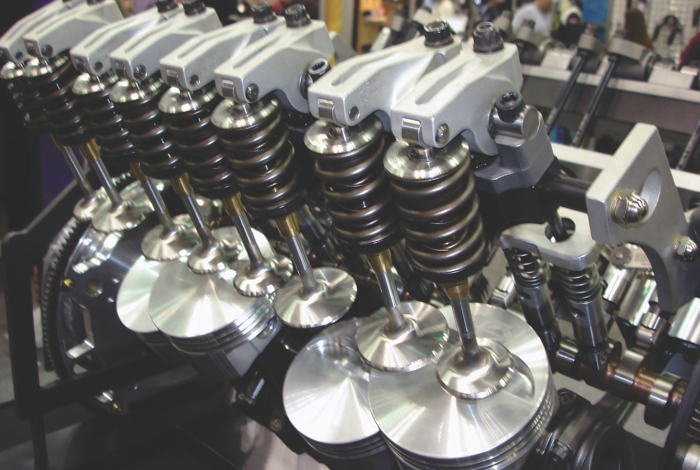
Event One: The intake valve begins to lift off its seat which triggers Event Two, the Scavenge Cycle. Intake valve opening ideally should match piston velocity. Reality proves that the maximum piston velocity is reached before the valve is fully opened limiting maximum air/fuel draw into the cylinder. Typical IVO is around 0-10° BTDC keeping valve overlap fairly balanced around TDC.
The intake valve does not reach maximum opening until approximately 105° to 115° ATDC (centerline) whereas maximum air/fuel fill occurs between 70° to 80° ATDC. How do we achieve ideal fill when faced with this situation?
Two methods can be utilized – first, more valve lift can create circumstances less than desirable. High lift camshafts require stiff springs coupled with a sharp cam lobe which can drastically shorten service life (non-roller camshaft).
The other option is an increased rate of lift. A fast lift rate removes the valve from obstructing flow which equates to high velocity charge motion.
High RPM requires additional air charge. This requires IVO to be earlier, allowing more time for cylinder fill. Earlier opening as discussed previously allows cylinder scavenging to aid in filling the cylinder and pushing out remaining exhaust gases. Fuel consumption can increase as some of the charge may pass through the cylinder and directly out past the open exhaust valve.
An early IVO increases valve overlap and allows the valve to be open further when piston reaches maximum velocity increasing VE. Application dependent on an early opening can also lead to a sluggish engine as exhaust gases dilute the intake charge (EGR).This reduces top end power as the exhaust gases take up cylinder space which reduces the amount of fresh air charge for combustion.
If the IVO is later, overlap is then reduced improving idle quality and low speed torque as well as sufficient engine vacuum. Later intake valve opening reduces the amount of intake charge causing a pressure drop in the cylinder as the piston is descending from TDC.
Tuning the IVO
Two methods can be utilized to accomplish this function. Adding duration or advancing the cam lobe. Adding duration extends both the RPM range and opens the valve earlier. The RPM range changes as the valve is held open longer and closes later ABDC. Adjusting the cam lobe timing creates changes on both the opening and closing side. Therefore if the valve is opened earlier, it will close earlier also, reducing RPM slightly.
Advancing the lobe can be used when RPM limits of the build prevent the addition of any further increase in duration. When the lobe is advanced, not only is the valve lifted further off its seat earlier in the intake cycle, it also aids in bringing the lobe center closer to match maximum piston draw.
One school of thought that exists in the engine building world is to first add as much duration as needed for the build to achieve the designed goals at an applicable RPM. Then if needed advance the intake lobe as far as limitations of valve timing events and overlap allow. Remember any change on the opening side of the lobe affects the closing side as well.
Acknowledgements:
Thanks to Matt Dickmeyer, David Vizard and Gary Goms for provided interviews or reference material; as well as Comp Cams, Lunati Cams and Crane Cams for online resources.
Editor’s note: Part three of this series will appear in an upcoming issue of Engine Builder magazine and will be available at EngineBuilderMag.com.

