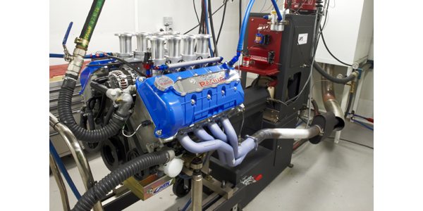
Most engine builders either have an engine dyno or rent the use of an engine dyno at someone else’s facility. The purpose of running an engine on the dyno is primarily a way of “protecting the investment.” This not only insures the workmanship of the engine builder but also the interest of the customer.
The engine builder wants to be sure that the combination of parts along with his or her expertise meets or exceeds the customer’s expectations of performance, power and reliability. The dyno also serves as a level of insurance to customers that the engine has met the criteria of what they wanted to purchase for their application.
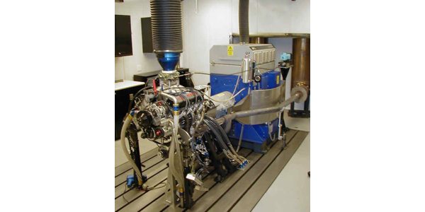
With the use of an engine dyno becoming more popular thanks to TV shows and magazine articles, little is still known about what really takes place in order to have a dyno facility. We see the “glory” as you might say, with the instrumentation and the engine bellowing in the background, making a rumble that would get the blood pumping in any true gearhead’s veins. But, there are a lot of factors that lay in the shadows and are never really noticed in order to properly dyno test an engine. There is an incredible level of planning, prepping, purchasing and proper orientation of components to achieve the return on your investment.
The power potential of today’s engines is incredible, of course. It is not uncommon for Engine Builder readers to build a street car engine capable of 2,000 horsepower. If you are wanting to purchase an engine dyno or simply want to know more about an engine dyno, here are a few things to consider.
There are different types of dynamometers, each appropriate for different applications and you should first consider the level of test capability you want. Testing capabilities refer to the test requirements you want to achieve such as torque, speed and type. There are four common types of absorbers to choose from for a dynamometer, which will dictate the level of testing based on torque and speed of an application.
The most common type of absorber is known as a water brake, which covers a wide range of testing capability. Water brake absorber engine dynamometers cover applications from diesel and industrial where there is low speed and high torque to gas performance where there is low torque and high speed. Water brake absorbers also work well for testing electric motors and small engines.
Water brakes are a great choice for performance diesel or gasoline markets where testing is primarily conducted in a range of sweep tests, though water brakes can become a bit challenging if precise engine control is desired. Water brake dynamometers are rated anywhere from 50 horsepower to 10,000 horsepower, and in some cases as high as 15,000 horsepower.
To get a basic understanding of how the water brake absorber works, water is churned inside the absorber’s housing and transfers energy through momentum and shear. The more water that can flow through the absorber the greater the braking force for testing.
The second type of absorber is known as an air-cooled eddy current. This type of dynamometer produces braking torque from a principle of eddy currents induced in rotating metallic discs immersed in a magnetic field. Air-cooled eddy current dynamometers offer precise control but for a short period of time. Being air cooled has its limitations because it has a short run time (usually three minutes) – as it heats up the braking capability becomes less. Once the “cold” capability is gone and the unit heats up, it will need to cool back down to ambient temperature again for proper control. Most air cooled eddy current dynamometers are used for specialized testing such as frictionless braking systems on buses and engine retarders on trucks.
The third type of dynamometer design is water-cooled eddy current. The water-cooled eddy current still consists of the same components as the air-cooled version: eddy currents are induced in rotating metallic disks immersed in a magnetic field with the exception that cooling water is provided. This type of unit offers a wide range of testing capability with an unlimited amount of run time as long as there is sufficient cooling water provided.
The water-cooled eddy current is easier to control and provides tighter control, faster response and quicker recovery time than a typical water brake design. The downside is they tend to be more expensive and do not offer the high torque at low speed capabilities as a similar water brake dynamometer.
There are two popular designs of water-cooled eddy current dynos known as “wet gap and dry gap” that a potential customer would need to be familiar with. The “wet gap” means that there is water in the gap with the rotor, which can produce a higher minimum load and higher dynamic inertia than the same “dry gap” unit. Water-cooled eddy current dynamometers can have a rated capability as low as 5 horsepower to a maximum of 2,500 horsepower.
The fourth popular type is known as an AC engine dynamometer. This type of dynamometer has by far the broadest range and highest potential of any other dyno. The downside is that it is more expensive than any other dyno mentioned. This type of dynamometer uses special AC motors that can provide both braking (load) and motoring (forced engine rotation).
The AC dynamometer can be custom built for specific requirements to test any small rotating device or tool, engine, electric motor, or powertrain component. The AC dynamometer is offered as a motor and drive package, but may be purchased as a regenerative or non-regenerative configuration. Regenerative means the power goes back on the electrical system when absorbing and non-regenerative means power is burned off in a load bank.
After considering the type of dynamometer you are interested in purchasing, the next step will be to design a test cell for that application. This is one piece of the puzzle that always seems to get overlooked. You spend countless hours of looking and budgeting for a piece of expensive equipment to realize that there is still quite a bit of expense left to ensure that it will give proper service and results. Designing the test cell is very important for functionality, safety, and repeatability. Here are several things that will need to be considered about the test facility before purchasing the dynamometer.
First, make sure to check with your local zoning laws and ordinances upon planning the construction. Then, try to orient the space needed for the construction of the test cell where it would best benefit the entire shop. This is where you want to have some sort of layout of the test cell and the equipment inside the test cell. The size of the test cell will be dependent on how big the dynamometer will be and application. Most performance test cells will be a 15 feet to 20 feet square. You need ample room to move and for placement of equipment such as the cooling tower, work benches, exhaust, entrance for dyno cart or overhead crane, data acquisition wiring, water inlets and outlets, and fuel lines.
Something else to keep in mind when installing a water brake absorber will be the placement of the cooling tanks and pumps, which are usually outside of the dyno cell and usually in a separate room. In addition, you’ll need a safe place for the fuel tank, usually in a separate room away from the dyno. And because of the fuel’s volatility, most dynamometer test cells will require a fire suppression system for emergencies.
Keep in mind that you will need to have some sort of “sound proofing,” and the operator’s platform will need to be in a separate room outside the test cell separated by explosion proof glass with a full view of the test cell. Something else to consider would be heating, A/C and humidity control along with an exhaust hood.
There are many blunders in the construction of test cells that have been recognized through the years by dyno manufacturers. This isn’t an exhaustive list, but here are the top five most commonly committed blunders.
#5
Inadequate Air Handling and Ventilation
Over-designing the HVAC (air handling and ventilation) system can lead to high construction and operating costs while under-designing makes it difficult to accomplish your test goals. A test cell has many health risks, including exhaust leaks, paint burn off, and engine blow-by – a proper air handling system will minimize the danger. Temperature control also affects power produced by the engine. Climate conditions in your area will help determine the equipment required for not only acquiring engine data but also elements such as freezing pipes and pressure hoses when the dyno is not in use. Make sure the operator’s area has proper HVAC also.
#4
Inadequate Water Supply
As horsepower of an engine increases so does the needed water supply. As the engine power goes up, municipal water supplies may be unable to provide adequate water required for the dynamometer and engine. This is where the design of the tanks and pumps comes into play from the installation of a water recirculating system.
Basically, a water circulation system uses one water tank to supply cold water to the dynamometer and another tank to hold the returning hot water from the dynamometer. The returning hot water enters the tank and will generally go through a cooling system before returning to the supply tank to be circulated again. When designing the water recirculation system there are things to consider such as pumps, motor size, flow rates, cooling devices, pipe size and electrical needs.
#3
Improper Planning and Budgeting
This relates to most of what we have covered thus far. Per square foot, a test cell can cost more than the dynamometer itself. Improper planning and budgeting of needed equipment for proper testing is often overlooked and miscalculated. Plan the test cell AND needed equipment before purchasing the dynamometer.
#2 Poor Test Cell Design
As mentioned before, the design of the test cell is very important. This is where a lot of work will take place. Placement of the test cell in relation to the shop along with the addition of maybe an overhead crane, workbenches, overhead exhaust hoods, etc. is critical. If the test cell cannot enhance the workflow along with testing adequately, then it becomes a hindrance.
#1 Safety
This is priority number one. Proper data acquisition systems can monitor potential hazards to the engine and operating system. Emergency shutdown and safety alarms should be in place allowing immediate shutoffs in case of a sudden unforeseen hazard, Be certain that the operator is properly trained to use the test cell and fluent in what to do when emergency situations arise.
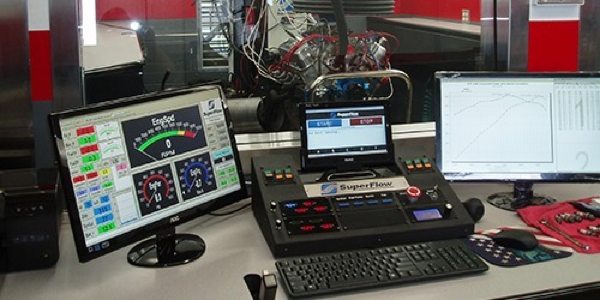
Another important consideration is the data acquisition system that will be used for the dynamometer. Most manufacturers have a proprietary data acquisition system for use with the type of dynamometer you purchase. Most performance engine dynamometers are capable of measuring data such as BSFC, coolant temperature, oil temperature, oil pressure, air/fuel ratio, cfm, air inlet temperature, barometric pressure, exhaust gas temperatures, etc. With today’s technology, data acquisition systems can go much further than traditional dyno measurements. There are choices for the level of data acquisition you want to use, so be sure you get the one that will benefit you best for your application.
One last important note, make sure that the manufacturer of the dyno provides great customer service that is a phone call away.