In the automotive industry, power and reliability have always been the quest of all engine builders and racers. There are many time-honored methods of increasing horsepower and the same with making engines more reliable.
But modifications can sometimes have residual effects and overtax another area of the engine, even compromising reliability. For example, raising compression causes more stress on the block and rotating assembly. Induction modifications that result in higher rpm can stress virtually every other part of the engine as well. An aggressive camshaft can tax every part of the valve train.
It seems that whenever a performance modification is done, other modifications must be done to support it, for the sake of reliability.
Some machining operations are well known to increase performance. Take cylinder wall finishes; testing has been done on different cylinder hone profile finishes, ring packages and their results well documented. Dyno tests show decreased blow-by and horsepower gains, while leakdown tests prove their benefit, when it comes to adding reliability.
I’d always wondered what certain machining and blueprint operations yielded the most percentage of gain. After machining probably thousands of blocks over the years, I’ve seen plenty of crooked decks, improperly located and aligned bores; main/cam bore alignment problems and poor dowel pin indexing.
There are some procedures that are widely accepted as to having benefits in both horsepower and reliability gains, but are rarely put to the test. One of these operations is lifter bore position truing. I’m sure it’s been back-to-back tested, but whoever has done it, is not sharing the results!
This is the basis of the test we decided to perform with the intent of reporting what happens, good or bad.
Where It All Began
When we started doing lifter bores, I found that they were probably the worst, in regards to location and size. Having corrected and bushed many of them, I thought it was time to do an actual dyno test. If anything, this would validate the procedure and provide solid data to back it up.
Shortly after I had finished the engine that I had built for this test, I was having a conversation with equipment salesman Dick Norum (Norum Equipment, Grantsburg, WI) and he mentioned that a local engine builder had told him that truing the lifters on a small block Chevy was worth 20hp.
Naturally, I was excited to hear this and asked if they actually had A/B test results to back their claim up. Well, Dick said, this guy doesn’t actually perform that procedure but it’s just his “opinion.”
Unfortunately, I felt that without solid data, this wasn’t something that I could use as a solid reference.
I said I’ve always heard similar stories but never with any actual data either. As luck would have it, I explained, I had actually built an engine with this back to back comparison in mind and that we’d be testing it soon.
Originally, I had planned on blueprinting the cam tunnel as part of the test but with a delay in tooling and a deadline to meet, it wasn’t going to be possible.
In hindsight, I figure more shops than not would just be doing the Lifter Tru process alone, so adding that to the test may have been adding another operation that was not as commonly done. I decided to correct the cam-to-crank centerline only if absolutely needed.
The Theory Behind Anticipated Gains
My thoughts are, the performance gains should actually come in a 4 immediate ways;
1. Correct index position of the lifters. This will give accurate timing events over the often incorrect stock positions. I’ve had blocks where the lifter bore wouldn’t clean up and index going from a .842˝ to a .875˝ and even some big blocks that wouldn’t all true up at .904˝. It’s not uncommon to have to sleeve several during this process.
Accurate timing events should help with cylinder-to-cylinder balance as well. Many times we are limited in tuning by one or two cylinders that are getting too hot on the EGT.
2. Windage control. The stock lifter bores, with the roller lifters I used, had .0035˝ clearance, on average. After index/bushing the bores, we will reduce that to .0017˝. Also, the lifter bushing will be extended both ways for more support and oil control.
With the bushing, we are able to meter the oil as well. A band is machined around the bushing and a reduced diameter hole is drilled. This provides 100 percent full time oiling, unlike stock, where the lifter can momentarily block the feed to the rest of the lifters at full lift. The type of lifter will dictate how large the feed hole is. On this application, I drilled them to .078˝.
By having full time oiling but a metered amount of oil to each lifter, I think it actually adds to reliability. I think it will stabilize the oil pressure as well, not having pulses in the lifter circuit.
Ring seal is often improved with windage control. Also, being able to use lower tension oil rings yields less drag. Hydraulic lifters having correct bore clearance is almost a requirement for proper function, especially with the spring rates seen today.
3. Reduced frictional losses. With the lifters correctly positioned on the lobes, there should be less side loading and thrust issues as would be if they are not running true. By extending the lifter bushings into the valley and down into the cam tunnel, there should be less load on the lifter body. With the full-banded lifter bushing, I installed them with the oil feed hole on the thrust side of the lifter. This will allow the oil pressure to help reduce friction too.
4. Stabilized ignition timing. I’ve seen some engines with cam/lifter problems so bad that they push the front cover out when you rev the engine. This will cause erratic timing and power losses. This is yet another area of improvement that we expect to see.
The Initial Build
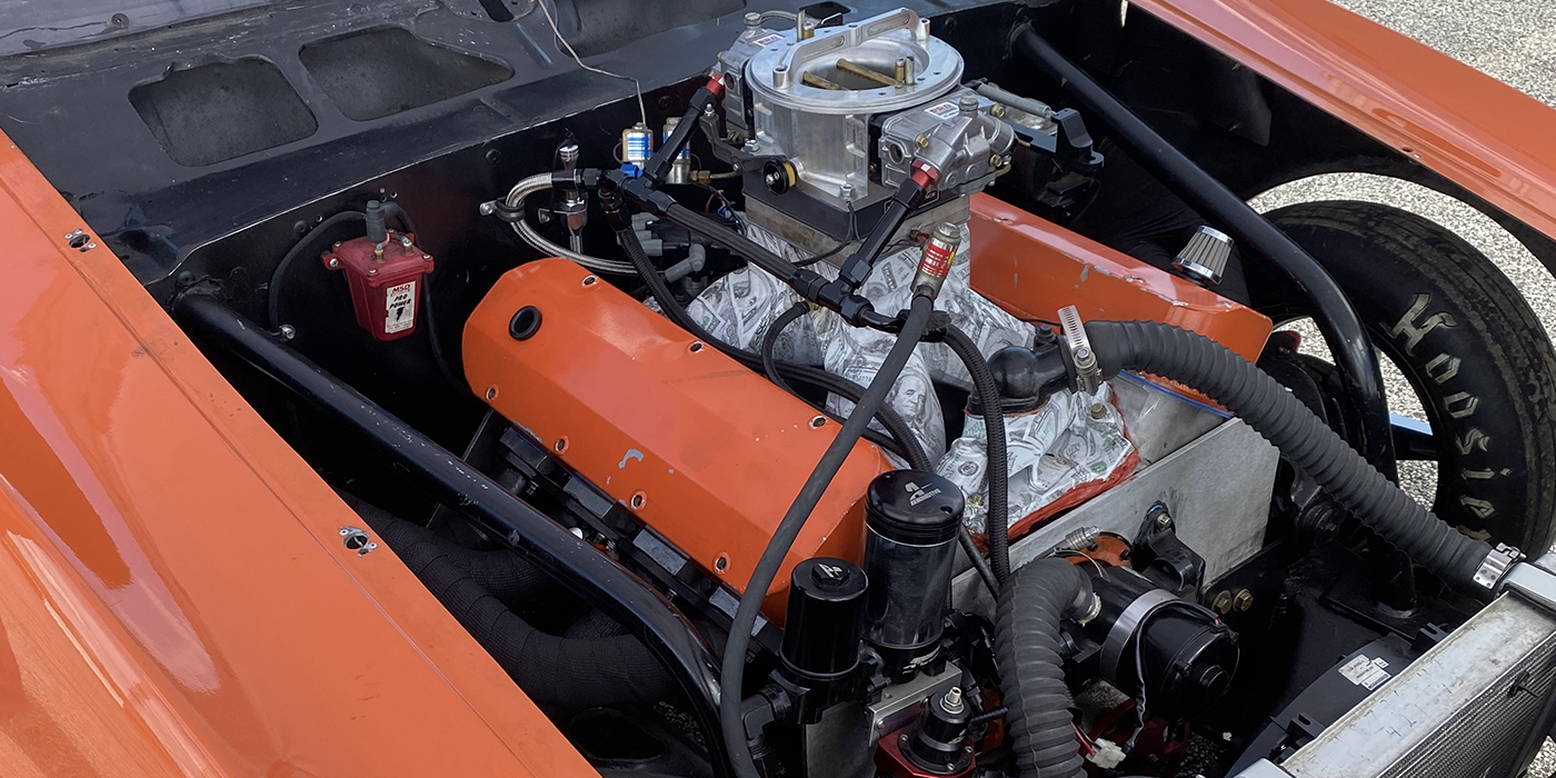
With parts I had in the shop, some that were donated by other shops and a few manufacturers helping out, I’d assembled a nice 383 Chevy shortblock that I thought would fit the bill.
I did all the usual blueprint machine work, installed billet main caps, line bored and line honed the mains, indexed/trued the decks, bored and torque plate honed the cylinders, trued the trans dowels and balanced the assembly. The only thing I omitted was the camshaft bore and lifter locating, saving those procedures for the B test. As it turned out, I just did the lifter bores.
For the sake of reliability and performance on the shortblock, I used a Molnar Technologies crank and rods, 10.8:1 Autotec pistons and a set of CR rings from Total Seal. I needed this engine to be consistent and repeatable. These parts are up for the job and then some.
For the remainder of the engine, I used a vintage set of Bowtie 23 degree aluminum heads and an Edelbrock Bowtie intake that I had on the shelf. My thoughts were that this had to be something that would rev to 7,000, as I feel that gains in all of the four areas would be exponentially better as peak power rpm increased.
I had Frank Windingstad at Advanced Performance, North Branch, MN, port the heads, with the only criteria being that it make over 500 hp at 6,500-7,000 rpm. One look at them and I knew he did the job, as always.
I profiled the 2.02˝/1.6˝ seats with stocking cutters; 4 angle intake, radius exhaust.
John at Erson Cams supplied the custom solid roller cam, with the same criteria that I’d laid out for Frank. We came up with a good grind that would work with the 1.5/1.5 rocker ratio. .645/.620 260°/268°@ 050˝ on a 108° LSA. An Avon Pro Gear billet timing set tied it to the crank.
The oiling system consisted of a Hamburger’s pan/pickup and a Milodon standard volume pump.
It was sort of a “stone soup” effort, honestly, with a bunch of industry friends coming together with parts and a helping hand to see this thing through. Everyone on board was pretty interested to see the actual results.
The Initial Dyno Test
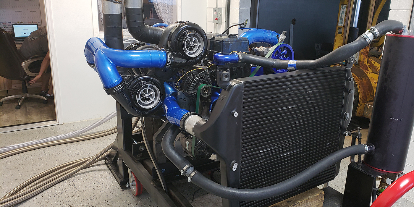
We installed the engine on Denny Nelson’s dyno on a Friday afternoon. We had a good weekend forecast with a few days of consistent weather. The plan was to get our initial testing done, bring the engine back to our shop, disassemble it, perform the lifter bore machine work over night, then reassemble and dyno the next day.
The initial test went well. One issue we had was that the timing was somewhat erratic. Even with a locked MSD Pro Billet distributor, the timing would retard 4-5 degrees when we revved the engine up to 3,500-4,000 rpm. At that point, it seemed to stabilize.
We made some pulls, re-adjusted the rockers and heat cycled it. It ran very well, overall. We were able to get 503 lb. ft. of torque and 521 hp. Even though the compression was only 10.8:1, we opted to run Sunoco 110 octane fuel for consistency.
There were a couple things that I noticed. First, the valve train did seem a bit noisy. I adjusted the rockers a couple times but it was the same. In order to get the best horsepower we could, we did have a couple cylinders into the 1,320 degree F EGT range. They were 80 degrees different from coldest to hottest.
The oil pressure on this test, at 4,000-7,000 rpm, showed a low of 49 psi, a high of 56 psi and an average of 53 psi. The oil pressure started to drop under 49 psi at 7,000 rpm.
After the initial test, the engine went back to Cedar Machine.
First off, I checked the camshaft to crank centerline. Even though the blueprinting tools had not showed up, I could have corrected the cam bores if needed. This would at least make the cam parallel to the crank, using oversize OD bearings. As luck would have it, it was right on, so we moved to the Lifter Tru operation.
For the lifter index/bore and bushing, I use the BHJ Lifter Tru, with my own tooling. I do this on a converted air float WVN seat & guide machine. My system uses a ball joint drive with roughing and finishing bore tools. I’ve found that leaving only a small amount to remove, on the final cut, causes no fixture deflection. It’s a fast method to do them and extremely accurate.
For the sake of this test, I’ll be using a .842˝ size lifter. Normally, a larger diameter would be a nice upgrade but I’m concentrating on consistency and using the same parts.
I modified the bushings as previously described, indexed and bored the block, installed them and final honed them to .0017˝ clearance. They are extended .150˝ in both directions.
The next day, the engine was reassembled with help from Dyno Denny Nelson, my nephew, Jake Davison and Ron Pratt, who was visiting from Sitka, AK. We managed complete assembly in just about an hour and a half.
The ‘After’ Dyno
Test – When It Gets Real
We loaded the engine up and took it back down to Denny’s dyno, a few miles away. Within an hour we were back up and running. We changed the oil filter, added 3/4 of a quart of new oil and put the oil from the previous test back in.
We then warmed it up to the same oil temp and cooled the engine back to our starting point that we’d been using.
My first observations were that the engine actually was a lot quieter, as far as valvetrain noise. The rockers sounded normal but there was noticeably less “clatter” from within. Secondly, the timing was very stable. It would roll back about 2° when I brought the rpm up and didn’t flutter around.
Just rolling the throttle, the engine was smoother to accelerate. After a couple of pulls, Denny said, “this is a whole different engine!”
We decided to, more or less, go back through the timing and jetting that we’d done on the original tests, to compare some results through the range of where we tuned it.
Within the first test, we showed an increase of 10 on horsepower and torque. We knew we were on to something. The air temp was 10 degrees warmer that the day before and we still had some jet to take out to get to where it had been its best on the A test. The EGTs were showing that we were a bit rich, as well.
We tried the same timing and jetting sweeps as the original test, showing increases every time. When we got to full timing advance with the leanest jetting was when we saw the biggest gains, as shown in the graph.
We ended up at 42 degrees of timing and 77/80 jets (with power valves), being the tune that provided the best power on each A/B test.
With the weather being a little warmer on the B test day, we actually did drop the jet some and get another 3 hp over the B test data that we used for the comparison.
On the best A/B test, we gained 20.5 lb. ft in the torque and 20.5 hp. Needless to say, we were all pretty excited.
In addition the gains, we picked up 5 psi on the average oil pressure and stabilized the exhaust temps by 20 degrees, with the range now being between 1,220° and 1,280°.
At 4,000-7,000 rpm, oil pressure saw a low of 55 psi, a high of 61psi and an average of 55 psi.
On the last pull, we ran it up to 7,500rpm and the oil pressure maintained 58 psi. It was still making 500 hp at that rpm as well.
It seems that everything we had anticipated played out like it was supposed to. It is possible that the engine could have initially made more power on the A test if we could have stabilized the timing but at that point, the oil pressure was starting to become an issue at the rpm we were running to. It was going to be small gains, if at all. We were already pretty hot on the EGT of a couple cylinders.
On the A test, we would have needed a high volume pump to help the bearings live and that would have probably cost more horsepower and had more windage loss.
By the same token, if we were to have dropped the pump pressure on the B test to where it was on the A test, we may have seen a further gain there.
We were looking for the real overall A/B data and not just 1 or 2 hp changes that could have been tuned in after the fact.
As far as our gains went during the second test, the torque gain occurred at the exact same rpm as the first run. The horsepower gain, however, peaked at 100 rpm higher and held the number over a 600 rpm span. My speculation is that it’s a combination of all four factors, timing events, windage ignition timing and friction but the windage and valve timing were the bigger of the gains.
Cylinder balance on the EGT show timing events being correct and oil pressure showing windage control.
We did observe the power gain, at its peak, to actually drop to half that, when it was 1,000 rpm past max HP. Giving that the gains were past the usable rpm, we felt that it was not as big a factor.
The Old ‘What’s In It For Me?’
These procedures, just from the reliability standpoint alone, offer many benefits. Customers will ask “Why should I do this?” Shops, too, ask “Why should I provide this service?” From the standpoint of both, it IS a somewhat costly investment – or so it may first seem.
Look at camshaft profiles these days. They are getting very aggressive and subsequently, tough on valve train. A roller lifter, properly riding on the cam has a much less chance of failure. A flat tappet cam, even more so.
I believe that most random lifter failures are probably misaligned parts far more than defective products. Just one lifter failure can cost much more than the initial upgrade of correcting the cam and lifter bores.
It’s a win-win situation. If the customer can gain horsepower and reliability, at a reasonable cost and the machine shop adds another profit center, there is no question. Everybody wins.
If a racer loses a lifter or cam lobe, then suffers a race loss and financial hit, guess what, the engine builder gets a bad rap. Somehow, it’s his fault that something that he didn’t even machine, but failed, can cost him money, time or even a customer.
At the time of these upgrades, a larger cam core can be added, larger diameter lifters can be accommodated and oiling mods done as well. It’s a chance to really upgrade what your customer has.
I think that most customers who would look toward the benefits of these gains would be operating their engines in relatively high rpm environments such as class racing and rules limited builds. These procedures, at their relative costs, play right into what these racers are looking for. They expect to make upgrades and like to see results. The promise of gaining 10 hp on a stock eliminator engine would have a racer plenty willing to pay $1,000-1,200 for that kind of return. Paying that after losing a cam for the assurance of not having that problem again, would be an easy sell too.
In closing, I find that blueprinting lifter bores is worthwhile on its own merits. Stable timing, oil control, cylinder-to-cylinder balance and valvetrain reliability are reason enough to do this. Gains in horsepower and torque are just the icing on the cake and a great selling point that racers respond to.
So, as far as the “unsubstantiated” claim of a 20hp increase, where do I stand now? Well, it seems that Ol’ Jack is on to something! ν
Special thanks to the team at Cedar Machine Service, North Branch, MN for the machining work; Grand Performance and “Dyno” Denny Nelson for the dyno service; Advanced Performance’s Frank Windingstad (Frankshaft Windinghigh) for the cylinder head porting; and Jake Davison Flood, Ron Pratt & Denny Nelson for their assembly and dyno assistance. Also, thanks to Tom Molnar (Molnar Technologies), Keith Jones (Total Seal), Randy Gilles (Race-Tec), Chris Gullickson (C&S Automotive), Chris Quilette (BHJ Equipment) and John Hartman (Erson Cams) for their assistance with parts.