In every aspect of an engine, strength is a very critical factor in the life span and performance level that it can achieve. One place in particular where strength is the most important consideration is the crankshaft. If we stop to consider the extreme forces that are placed on it with every revolution of the engine it quickly becomes apparent that the job it’s tasked with is no simple feat. Ensuring that you have the best material and design for a given application can be the difference between producing the results you’re after or dealing with a ton of grief.
Metallurgy and Processes
We’ll start our discussion by taking a look at the various strength characteristics that make up the materials cranks are made of and also the difference in the production process. Making a cast crank involves pouring molten metal into a mold to produce a raw casting. The casting comes out of the mold closely resembling its final shape and therefore doesn’t require as much finish machining when compared to a forging.
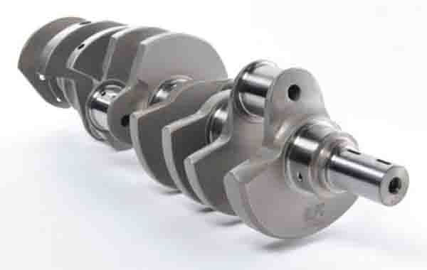
Cast iron cranks achieve a tensile strength of 70,000-80,000 psi and by adding additional carbon to the iron gives us nodular iron, which comes in a little higher at around 95,000 psi. A number of aftermarket manufacturers produce cast steel crankshafts which have an even greater carbon content and are rated at a tensile of about 105,000-110,000, which makes them more dependable for higher output and stroker applications. Most of these cranks will have a manufacturer suggested power ceiling of around 450-500 hp or so, although they have been pushed beyond that mark because of usage in certain competition venues where the rules require a cast crank (we’ll get more into that later).
Forgings are made by placing a heated piece of billet into multi-ton presses that then compress it into shape with forging dies. It is the compressing action that makes a stronger end product than a casting by achieving a more consistent or uniform grain structure (commonly called grain flow) of the material.
Unlike a casting though, the forging requires more machining and finishing steps which, in conjunction with material costs, creates a more expensive part to make. Forged crankshafts are produced in many different strength ranges depending on the material. Factory forged cranks are made from steels such as 1010, 1045, and 1053, which have a tensile strength of 100,000-110,000 psi. The tensile ratings are similar to cast-steel but the elongation rating is more than triple. This makes the forging less brittle.
Aftermarket steel cranks are made in 5140, 4130, 4140 and 4340 alloys. The basic aftermarket grade steel is 5140 and has a tensile strength of about 115,000 psi. This material can be cost effective for budget builds, but isn’t used as much due to the increasing availability of stronger alloy cranks that are becoming more affordable. These include 4130, 4140 and 4340 forgings, which have tensile strength ratings of approximately 120,000-125,000 psi and up to 140,000-145,000 psi for 4340.
The main differences between these alloys is the amount of chromium, carbon and molybdenum used in their compositions with nickel being added to 4340. Another twist (literally) to forgings is if the crank is manufactured by a twisted or non-twisted process. Since forged cranks are pressed into place on a die there are two different methods used to accomplish this. The easiest method is to forge one crank throw at a time in a flat forging die. The crank is then twisted, and the die forges the next throw.
In a non-twist forging, all four throws are forged at the same time, thereby eliminating the twisting procedure but it requires a more complex die using this method. Most manufacturers claim that non-twist forgings reduce internal crankshaft stresses using this process because there is less disruption of the internal grain structure of the material. There are differing theories regarding this but there are very few manufacturers of performance cranks that use the twisting process due to the current tooling that is available.
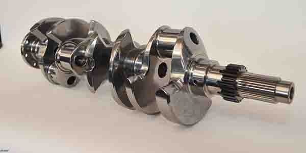
Now let’s get into billet cranks. This type of crank is machined from a solid bar of high strength steel alloy as opposed to being compressed into shape with presses and dies. Materials used for these cranks is usually 4330M, EN30B and 4330V. Tensile ratings run in the 160,000-165,000 psi range. All other factors being considered, the only real drawback to a billet is the cost. While they are more expensive than forgings there are benefits that can be had by utilizing a billet. Since the shape and all other dimensions are machined, billets provide the ability to produce a crank with journal sizes, counterweight designs and stroke lengths that may not be readily available in a forging.
There is no question that the strength is there with a billet and they are used in numerous applications where the fatigue life of the crank is a concern. Since we touched on the aspect of fatigue life we’ll use that as a gateway into the topic of ductility.
All cranks flex under the tremendous loads placed upon them. Ductility is the crankshaft’s ability to bend without cracking and return to its normal shape without being permanently affected. Combustion pressures, piston speed and total weight of the components attached to the crank all work to exert these loads. If we examine the physical operation of an engine from the perspective of the crankshaft, we see that it is moving components from zero to max RPM and back to zero twice during every revolution. Consider with this the pressures added from combustion and the inertial factors of piston speed (weight of the components times acceleration) and we see just how important it is to have a crankshaft that offers the best combination of strength and ductility for the given application. This, however, is another area where there are differences of opinion within the industry regarding the forged/billet strength question.
Some experts state that a forging will be stronger than a billet and others believe the opposite. There are various arguments to support each train of thought, but in my opinion, the billet piece will offer superior strength. No matter which camp you are in, the main objective when choosing a crank should be based on the requirements of your application that are necessary to achieve the longest life possible.
Crankshaft Design
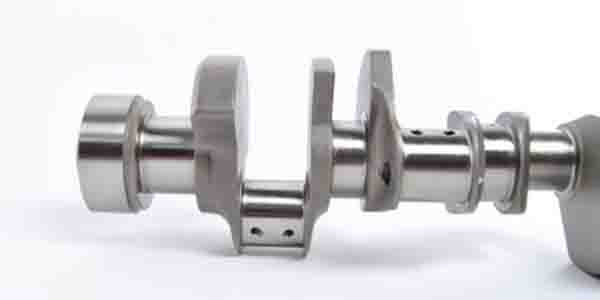
Counterweight shape and location affects the main bearing loads and balance of the crank. Bearing load is self-explanatory but balancing is an area of variables. Crankshaft manufacturers do an excellent job of providing products that can usually be balanced fairly easy around a specific bobweight target. I use the word usually because of the enormous number of components available which make up the rotating assemblies. Piston size, ring dimensions, connecting rod type and rod bearing design all determine the bobweight that the crank must be balanced to.
Materials that these parts are made from also vary when it comes to the weights, an aluminum rod is much lighter than a steel rod, hypereutectic and forged pistons have differing weights as well as the other parts that make up the rotating assembly.
As an example, let’s look at a couple of small block Chevy engines that will both use a 3.480 stroke crankshaft. Let’s say engine one is being built for a 305 sprint car. The pistons are a 3.796 bore, thin ring stack, I-beam rods and chamfered rod bearings. Depending on the brand, this combo should have a bobweight of around 1590 to 1610. Engine two is a 377 cube for a street rod with 4.155˝ bore pistons, thicker ring stack, H beam rods and chamfered bearings. Again, depending on the brands used, this combo should have a bobweight in the range of 1760 to 1780. Both engines will be using the same part number on the crankshaft but with close to 200 grams difference in the bobweights we can see that they are going to each require a different approach on balancing.
This example shows how the same crankshaft can end up simply having some material removed from the counterweights of one by drilling whereas the other engine may need a piece of mallory added to achieve the correct balance. Another area when dealing with aftermarket forged cranks is a larger, smooth radius between the rod journals and counterweights that is used for additional strength in this location. Cranks with this design feature will require the chamfered (or narrowed) rod bearings that were referenced in the example of balancing combinations.
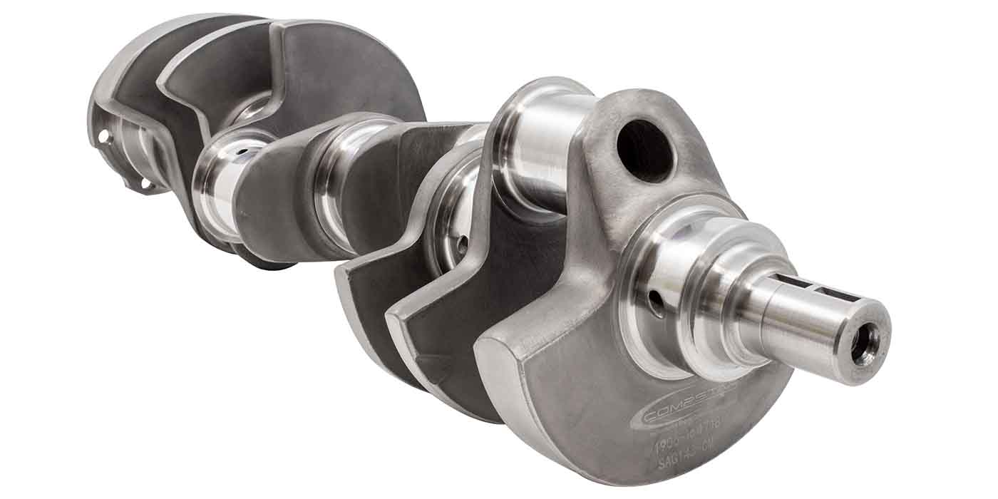
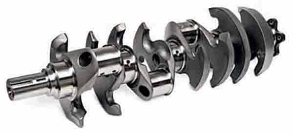
Counterweight shape also has an effect on windage in the oil pan. In years past, manufacturers would machine what was referred to as a “knife edge” finish on the leading edge of the counterweights but have since moved to a more rounded or “bull nosed” shape after discovering that sharp angles would deflect the oil as opposed to allowing it to flow around the counterweight.
A sharper edge can be useful on the trailing edge of the counterweight to help produce a more aerodynamic shape, however. Additional counterweights added to the center of the crankshaft can also help in higher output and competition engines by reducing the amount of crank deflection in high RPM and forced induction applications. While this also adds to the overall weight of the crank it is worth the trade off for the durability benefits because stiffness is more important than weight.
Continuing on with durability in mind brings us to the subject of journal overlap. This is the amount of how much the crank’s main and rod journals overlap each other. The more overlap that is present in the crank, the stronger it will be. As stroke lengths increase, it moves the rod journals farther away from the mains, thereby reducing overlap and also some of the strength. Another instance that can reduce overlap is in applications that utilize smaller diameter main and rod journals to reduce bearing speed and/or provide additional clearance by being able to use a smaller connecting rod.
Oiling and Heat Treatments
There are a number of treatments that can be performed to relieve stress and also increase the strength level of a crankshaft. They can be chemical, vibratory, cryogenic, heated, etc. but we’ll discuss the two most widely in use at this time – induction hardening and nitriding.
Nitriding is accomplished by heating the crank in an oven with nitrogen and other gasses present. Ionized nitrogen is vacuum deposited onto the surface of the crankshaft which penetrates the metal during this controlled heating process and increases the hardness and fatigue life of the crank.
Induction hardening is done by generating rapid heat in the crank by using a high frequency alternating magnetic field that provides the surface penetration required to strengthen the crank.
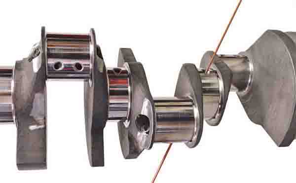
We’ll round out our discussion with the oiling passages of a crank. Pressurized oil from the main bearings is delivered through passages drilled into the crankshaft to the rod journals in order to lubricate the rod bearings. This is one more area that has seen changes over the years as engines has been constantly upgraded through technological advancements and increasing power levels.
At one time, many performance cranks were cross drilled all the way through the main locations in an effort to equalize oil flow to the bearings. While this can be acceptable in an engine that will operate at a lower RPM level, industry experience has proven that it has the opposite effect at higher engine speeds by actually pulling oil out of the holes to the rod journals through centrifugal force.
Aftermarket cranks are now made with oil passages that are drilled in specific angles from the main journals to the rod journals in order to insure more consistent oiling and no longer employ the cross drilling in the main locations. The openings of the oiling holes in each journal also have a generous amount of chamfering to help promote oiling efficiency and eliminate any sharp edges.