Understanding how rocker arms work
The rocker arms in an engine have one simple but very important function: transferring the opening and closing events from the camshaft to the valves. Well, we all SAY it’s simple, but is it? Questions about what works best are still asked by even the most seasoned professional. With all of the math and all of the options, understanding how rocker arms work is worth talking about.
They do so by converting the radial movement of the cam lobe into linear movement at the valve. The amount of lift that is achieved is determined by the ratio of the rocker arm, which will dictate the actual distance that the valves travel from the valve seats.
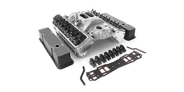
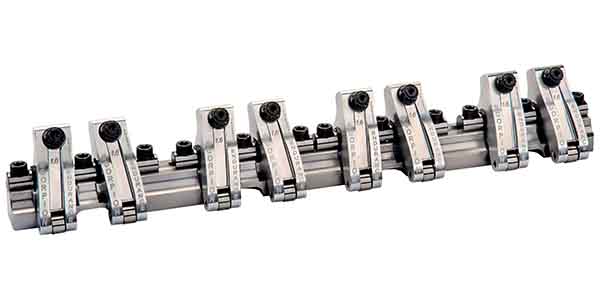
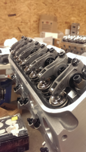
You have numerous options to choose from in aftermarket rocker arms for just about any pushrod-type engine and overhead cam designs as well. There are stock replacements made from stronger materials; roller tip rockers that maintain the OEM-style fulcrum mounting but have a roller tip to reduce friction at the valve stem; stud or pedestal mounted full rollers that utilize a needle bearing or bushing at the fulcrum and also have a roller wheel at the tip; and shaft-mounted rollers for higher output applications that need greater stability. There are also several factors to address when setting up the rocker system to ensure proper operational stability and alleviate any possible clearance issues with the valve train so let’s take a look at some of these areas.
Rocker Arm Alignment
Alignment of the rocker arm is extremely important – any deviation from the correct contact point of the valve stem can cause accelerated wear at best and component failure at worst.
The contact point on the valve stem should begin toward the intake side of the cylinder head with the valve closed. As it starts to open, it should roll out past the center of the stem toward the exhaust side of the head at half lift and then from half lift to full lift it should return to its original starting point toward the intake side. The actual amount of tip travel across the valve stem is affected by the amount of lift at the valve but you want to make sure that all the travel is in the center of the valve stem and not biased to one side more than the other.
An easy way to get a visual witness mark of the travel area is to color the valve stem tip with a permanent marker, install the rocker with a checking spring in place, adjust it to zero lash and rotate the engine to completely cycle through an intake and exhaust event. When you remove the rocker, it will have rubbed the coloration off the tip and you will be able to see the travel distance and location. If the travel area is located too far toward the intake or exhaust side then you will need to adjust the push rod length accordingly. If it’s too far inboard, the push rod needs to be lengthened, if it is more to the outboard side it should be shortened.
The other alignment location will be from the front to rear of the engine. The rocker contact point should be centered on the stem and this can be adjusted by locating the guide plate for proper alignment (adjustable plates are available if the standard guide doesn’t allow you to achieve correct alignment) and by using shims or offset rockers on shaft-mount systems.
On some shaft-mount applications, an offset rocker must be used in order to get the correct location. This situation usually occurs when using cylinder heads with larger runner sizes or different valve spacing. Getting the alignments correct will provide better valve guide longevity and keep the rocker arms from damaging the valve tips.
Clearances
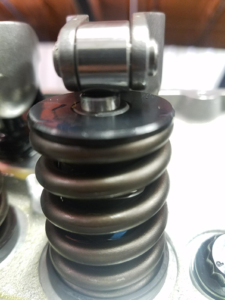
When utilizing higher valve lifts through cam lobe design, rocker ratio or a combination of both, using a pushrod that has a 210-degree tip radius will provide additional clearance between the rocker cup and pushrod and eliminate the chance of the pushrod binding during operation at these larger lifts.
While we’re on the subject of pushrods, always make sure that there is no point of contact between the cylinder head and pushrod throughout the full range of valve movement when mocking up the engine. If there is any contact present, it will require modifying the head or using a smaller push rod diameter (not advisable for high output engines) or possibly going to an offset lifter or rocker arm in order to move the push rod away from the contact area of the cylinder head.
The next point we’ll discuss is the valve spring retainer and rocker arm. There has to be sufficient clearance between the rocker arm body and the outer diameter of the spring retainer to ensure no contact occurs in this area. You must also check for any issues with the top of the retainer. If a problem is present there are two solutions.
One is to change the spring retainer diameter, which could involve changing the spring as well, or possibly changing the style of retainer that is being used. Valve spring retainers come in different styles. Some can be flat across the top while others may be recessed in the center around the valve locks with the outer portion of the retainer being taller. Another scenario that can affect this is if retainers or locks are used that add more installed height in order to achieve the proper amount of valve spring pressure for the application. In that instance it would be more favorable to change the springs (providing a spring is available, that will give the required open/closed pressure) and use a standard height retainer and locks.
The other option for this is to change the rocker to a design that has more clearance made into the body of the rocker arm. Often the choice comes down to which solution is more cost efficient when faced with this situation, but either way, you must make sure that no contact exists between these two components.
If you are using a stock replacement design or a roller tip rocker arm in conjunction with higher valve lifts, such as in a circle track application that requires stock-appearing rockers in the rules, for example, always make sure that the slot in the rocker arm has enough clearance with the rocker stud to accommodate the amount of lift. There are also pivot balls and rocker adjusting nuts that are designed for these type applications that increase oiling at the fulcrum point to aid in cooling and extend service life.
In that same train of thought, there are kits available from various manufacturers that allow you to convert pedestal-style OEM design systems such as on a Dodge or Ford to a rocker stud/guide plate design that will allow you to use high performance adjustable rocker arms without requiring machine work to be performed on the cylinder head as well as trunion upgrade kits, such as on the GM LS engine, that allow for greater lifts and less friction than the factory parts.
Whenever you’re making a big change to the rocker system of your engine, pay close attention to the specific details of the installation process. If you’re installing roller rockers on a stud-mount application to replace the factory items it will be pretty straightforward but there are still some instances with additional steps to perform. For example, a Ford FE engine oils the rocker shaft through the cylinder heads. When installing adjustable roller rockers on this engine, you will need to restrict the oiling passage in the cylinder head.
If you’re installing new roller rockers or a roller shaft set up on your engine don’t forget to allow for the additional space that these rockers require under the valve cover. Many times the stock valve covers will not be tall enough to clear and factory baffles seldom ever fit in the reduced area between the rocker arms as they did with the OEM units.
The point here is to check everything carefully and follow all the manufacturer’s instructions so that your new system works properly without any operational issues or failures.
Rocker Ratios
Understanding rocker arm ratios is really about simple math. Rocker ratio is the distance from the trunnion centerline or pivot point to the centerline of the valve contact point divided by the distance from the centerline of the push rod cup to the centerline of the trunnion. It is this ratio that multiplies the lobe lift of the cam into the lift that is achieved at the valve.
In order to determine how much valve lift you will get by using different ratios you just multiply the lobe lift by that particular rocker ratio. As an example, let’s say that the cam has .510˝ lift on the intake and .525˝ on the exhaust with a 1.5:1 ratio rocker arm. If we divide .510 by 1.5 it shows us that the lobe lift of the camshaft is .340˝ on the intake, now we divide .525 by 1.5 to find an exhaust lobe with .350˝ lift.
If installing 1.6:1 ratio rocker arms, the calculation would give us .340 X 1.6 = .544˝ and .350 X 1.6 = .560˝, so the same 510/525 lift cam would net valve lifts of 544/560 with a 1.6:1 rocker and allow us to produce additional power.
The same holds true if we go in the opposite direction. We’ll use an example of a race engine with considerable spring pressure and use 1.3:1 ratio rockers for break-in. Multiplying .340 X 1.3 gives us .442˝ and .350 X 1.3 is .455˝. We have now used the rocker ratio to reduce the lift and simultaneously lowered valve spring pressures to ease the break-in load on the engine.
Manufacturing Materials
Rocker arms are constructed of various materials to perform in different applications. OEM stamped steel replacement units are available for stock or mildly modified builds. For rule- limited competition builds that have higher valve lifts and will see more rpms, stock appearing steel rockers are available that have longer slots and are carburized to increase their strength. They often look like stock parts to meet requirements of many racing classes/series but feature nitrocarburized surface hardening to achieve the strength of ceramic-coated parts at a fraction of the price. These are ideal for racing applications using extreme valve spring pressures, say experts.
Steel roller tip rockers perform well in most street applications and are also used in some competition engines where the rules will allow them. Die cast aluminum roller rockers are a good, economical choice for engines that have less than 400 lbs. of open spring pressure. Extruded aluminum rollers are generally good for 700-750 lbs. of spring pressure, but some are rated considerably higher than that from manufacturers that have specifically designed them to perform at higher spring pressures and rpms. Steel roller rockers have the ability to handle the highest pressures and are stiffer than aluminum with greater levels of fatigue strength.
When choosing a rocker arm for higher output engines always check the pressure rating and contact the manufacturer if you have specific questions regarding the durability or fitment to your application. ν