Carburetors are still a viable and valuable component for atomizing fuel.
It is amazing that the carburetor has been around for well over 100 years. A small yet unique invention by the Holley brothers in the early 1900s provided the concept of what we use today.
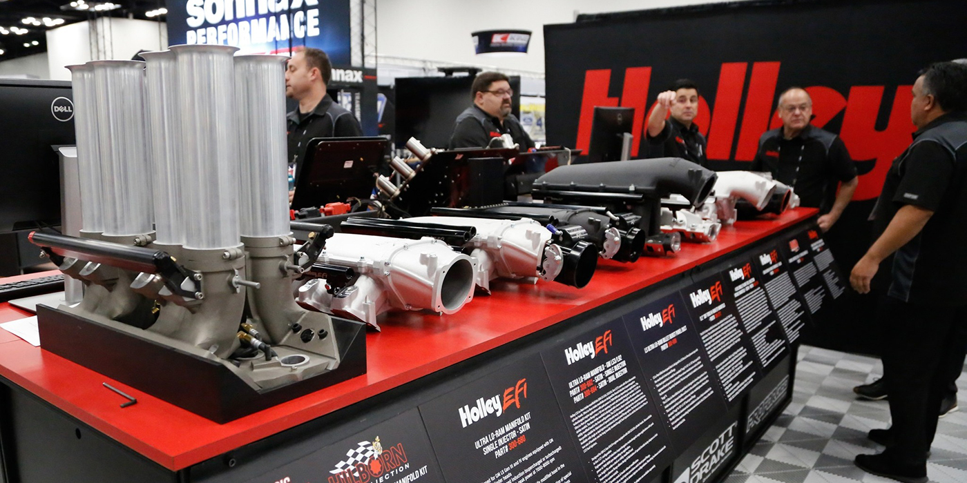
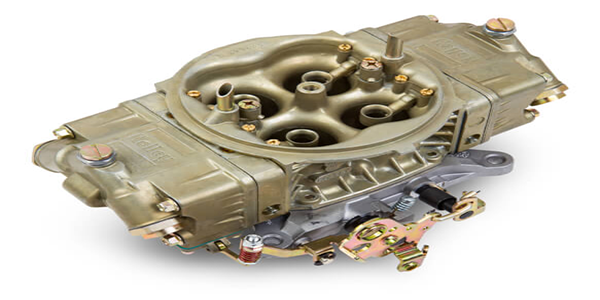
 Holley became recognized in the high performance market when it released the first 4150 series carburetor on the Ford 312 engine in 1957. Ford became extensively involved in NASCAR and, in the late 1960s, contracted with Holley to build a bigger carburetor for the 429. In 1969, Holley released the 4500 series carburetor known as the Dominator series that produced 1150 cfm. The 4150 and the 4500 series carburetors have been the premise of what most engine builders choose for high performance applications.
In 1986, while working at an automotive dealership, I realized that most all automakers had incorporated the use of fuel injection and abandoned the carburetor. Several years later, Holley introduced the Pro-Jection system in the aftermarket and it seemed that the carburetor’s importance for performance use was on its way to being something of the past.
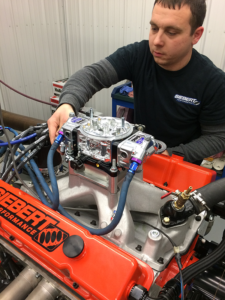
 Now, when you go to the race track you see the pit crew grab the laptop to make adjustments, just as in years past, we removed the air cleaner and tweaked on the carburetor or the distributor. However, even though modern fuel injection systems do have their advantages, the carburetor is still considered superior for a wide range of applications. The key to carburetor tuning is knowing exactly how it functions.
It is common to see someone take a carburetor out of the box and bolt it on, crank the engine and start turning screws and making adjustments. While they may have a basic knowledge of the carburetor system, do they really grasp what is taking place to atomize the fuel?
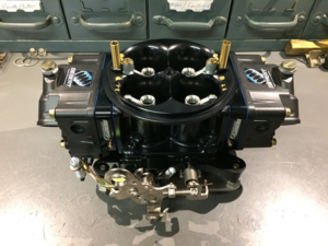
A carburetor is an “air-fuel metering device.” The purpose of which is to “properly” atomize the fuel. This is why selecting the right carburetor for the application is very critical as to how it will perform. It can be intimidating and there are many intricate pieces of the carburetor system that need to be explained that will help in understanding their purpose and how that equates to performance with drivability.
The carburetor is controlled by pressure differences. In the main body of a four-barrel carburetor there are four venturi. The shape, size and length of each help determine airflow and fuel flow into the engine. The term venturi came from its inventor Giovanni Battista Venturi. He had no interest in the internal combustion engine whatsoever – in fact, he was noted for his work as a physicist and priest – but, he discovered that if air moves through a tube that looks like a double ended funnel that the air velocity would change. As air moves through the narrow portion of the tube, the pressure decreases causing the velocity to increase. This formed the basis for all carburetor designs.
The low-pressure area in the narrow diameter portion of the venturi forms a suction. This area would seem to be the ideal place to siphon fuel. So, if you connect a small siphon tube in this area to a reservoir of gasoline, the fuel should be drawn from the reservoir into the air stream of the venturi. But, it would take a lot of airflow to have enough signal to siphon. There would not be a sufficient pressure drop at lower air speeds to siphon fuel from the reservoir. This is where the air flow needs a “boost.” Instead of reducing the size of the venturi, a booster venturi is used to amplify the pressure drop.
In a typical carburetor, the booster venturi is placed right above the small portion of the main venturi. As the throttle blades slightly open, the air velocity is magnified in the booster which creates a suction to draw fuel in from the fuel bowl. The amount of fuel that is drawn from the fuel bowl and enters the booster is controlled by the main jet. A main jet is a calibrated orifice of a specific size. The main jet needed would depend on how much fuel the engine desired to make power and can be changed to allow more or less fuel being drawn into the venturi.
A key point to remember here is that fuel has to be atomized. Fuel being drawn into the venturi through the booster has to be a very fine mist, not just droplets. To help emulsify the fuel there is a passage between the booster and fuel bowl that leads to an air bleed on top of the main body of the carburetor. The suction force that draws fuel from the fuel bowl through the booster also pulls in air from the air bleed. This mixture of air helps atomize fuel into tiny droplets before entering the air stream.
The air bleeds also give control over fuel flow, relieving some of the suction signal before it exits the discharge nozzle. By changing the size of the air bleed, the suction required to initiate fuel flow can be altered. If the air bleed is increased, the amount of suction needed to initiate fuel flow is increased. If the air bleed is decreased, the amount of suction needed to initiate fuel flow is decreased.
Air bleeds on a production-style carburetor are specific and therefore fuel will flow at a specific vacuum. Aftermarket and performance carburetors have changeable air bleeds for tune ability of specific engine requirements. Altering the air bleeds will alter the air/fuel ratio of the engine. If a bigger air bleed is used, more air enters the fuel stream causing a leaner mixture.
The idle circuit can be somewhat complex also. Think of the “idle” circuit as a way of controlling fuel and air to allow the engine to operate at its slowest speed. The combination of components such as camshaft and intake manifold design dictate an engine’s slowest speed requirements whether it is for performance or daily driving. Do not think of the idle system metering screws as a way of controlling the air/fuel ratio but think of it as a way of how much of the air/fuel ratio reaches the intake manifold.
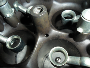
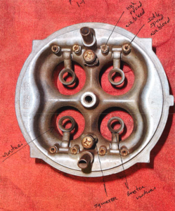
The idle circuit of the carburetor works very similar to the main fuel metering functions that supply the booster venturi. Underneath the butterflies of the carburetor baseplate are small passages that connect to the idle circuit. While the engine is idling and the butterflies are closed, the vacuum formed underneath the carburetor pulls on the idle circuit through the small passages. One passage is a small hole and the other is a slot in the baseplate at the butterfly. These passages go through the baseplate into the carburetor main body that are fed by the metering block, which is controlled by the metering screw.
In simple terms, this is how the idle circuit functions: inside the metering block is a passage that is supplied with fuel from the main jet fuel passage. Fuel enters the small passage and travels toward the top of the metering block where it is controlled by an idle restriction, which is very similar to the functions of the main jet. The idle restriction purpose is to regulate fuel flow. As fuel leaves the idle restriction it is mixed with air from the idle speed bleed in the top of the carburetor. The idle speed air bleed works the same as the high speed air bleed of the main metering system. The fuel is emulsified with air and sent down the metering block through a separate passage, which leads to the idle mixture screws.
The air/fuel mixture is regulated by the mixture screws, which supply the small passages underneath the throttle blades or butterflies. The idle mixture port is the small round passage at the throttle blade. One important thing to remember is that if you turn the mixture screws all the way in, which will cut off air/fuel flow to the idle circuit passage, the idle transfer slot will still have fuel supply. The mixture screws do not control the fuel that will be pulled in through the idle transfer slot. Air and fuel that exits the transfer slot is in proportion as to how far the throttle blades are opened from the idle screw on the throttle linkage.
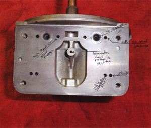
While the engine is idling and you accelerate by opening the throttle blades, you have to have a short period of enrichment to overcome the loss of air speed velocity. This transition period occurs off idle right before fuel starts flowing through the main metering system. This is also known as an off-idle stumble. There has to be a way to overcome the loss in velocity through what is known as a “pump shot.” Manifold vacuum is good at an idle and when you open the throttle blades velocity drops momentarily so the air is stalled. The accelerator pump circuit delivers a shot of gasoline above the throttle blades to help bring engine speed up so the air velocity can cause fuel to flow through the main metering system.
On the bottom of the float bowl is a diaphragm actuated by a linkage arm with a cam. As the throttle is opened, the cam actuates the arm and pushes on the diaphragm, which sends fuel through a small passage in the metering block to the squirter in the top of the baseplate that delivers the fuel shot. The fuel delivered by the pump shot can be altered by the squirter size and cam shape on the linkage arm. These adjustments to the accelerator pump circuit are necessary because of the carburetors use in different applications, such as large camshaft profiles where there is low velocity at idle.
Another function of the carburetor is known as power enrichment. Power enrichment is well-known to most carburetor enthusiasts as the power valve. In a perfect world, as long as there is good signal to the booster venture, fuel would flow from the main metering system and supply the engine based on the position of the throttle blades.
But what would happen if the signal weakened but the demand increased? Let’s say for example that you are driving down the road and the engine is performing well. The road changes to a steep grade incline for an extended period of time. As the vehicle goes up the grade the rpm drops, but the fuel demand is greater. The power valve helps supply fuel when the signal strength weakens. A power valve operates on the premise of intake manifold vacuum. It consists of a spring loaded diaphragm with a valve and seat assembly screwed into the metering block. There are a wide range of power valves for different applications. On most Holley carburetors the power valve has an operation vacuum of 6.5 inches.
While there is plenty of intake manifold vacuum on the backside of the diaphragm, the valve in the seat remains closed. As soon as the manifold vacuum decreases, the spring pressure in the diaphragm is overcome and the valve lifts off the seat. When the manifold vacuum reaches 6.5 inches it will open. This allows fuel to flow from the main well through the metering block through a passage known as the PVCR (Power Valve Channel Restriction) orifice to the main metering circuit to exit the booster. The PVCR serves as a “jet” to control how much fuel enters the main metering circuit from the power valve.
With most carburetors there are many ways to fine-tune performance for your application. The calibrations can be effortless if the right tuning procedure is performed. While the basic knowledge of the carburetor is helpful, knowing what to correct when fuel distribution problems arise is the real key.
One hint would be to read the instruction manual before installing. If the carburetor is properly chosen for the application, the instructions will help in eliminating problems because they are overlooked before the install.
Take an opportunity the next time you perform a rebuild on one to study the main body, metering block and baseplate to get an idea of the distribution channels and how they perform. ν