What to Know When Rebuilding Ford’s Powerful 3.5L Six-Cylinder Engine Platform
Originally named TwinForce, Ford had a simple and specific directive with the development of its new engine family: “Build a low-emissions vehicle, with good fuel economy, that performs so well that the driver forgets they are driving a low-emissions vehicle with good fuel economy.” From that concept came the EcoBoost.
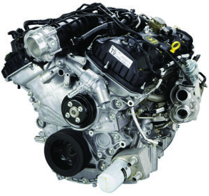
The EcoBoost is a gasoline turbocharged direct injection (GTDI) engine that incorporates three fuel-saving, performance-enhancing technologies—forced air induction via turbocharging, high-pressure direct fuel injection and variable cam timing.
From my own experience with my daughter’s F-150 I can attest to Ford’s success in accomplishing its goal with the 3.5L. While hauling a trailer with two horses, saddles, a tack box, hay, feed and who knows what else, I would have never thought anything other than a V8 was under the hood of her truck.
Official EcoBoost production began on May 19, 2009 at Cleveland Engine Plant No. 1. There are presently two Generations of the 3.5L EcoBoost engine and there are three versions of the first generation. The transverse mounted Gen I and the Gen II engine (which came out in 2017) will not be a part of this article. However, the F-150 EcoBoost, which had the largest volume of production and remanufacturing, provides plenty to talk about. I’ll call them Gen IA and Gen IB for ease of identification. The chart on page 36 gives you a road map of the vehicle applications.
The F-series EcoBoost 3.5L V6 uses two BorgWarner K03 turbochargers which can spin up to 170,000 rpm and provide up to 15 psi of boost. Just to get our heads wrapped around the impact turbo charging has upon an engine with 10:1 compression ratio at sea level with 15 psi of boost; it now has an effective 20:1 compression ratio, running on regular fuel. The 3.5L Ecoboost has 10:1 compression ratio.
Cylinder Block
The cylinder blocks for both versions of the Gen 1 engines are the same. You will want to be aware of the bottom of the cylinder block prior to doing any machining, especially the cylinder bore. It appears as though there may have been a glitch in the machining program or the cutter choice, or some evil engineering joke on the reman world. The bottom of the block/pan rail is not flat – there is a shallow ledge every bit of .030˝ (see Photo 2, right) that has the potential of giving your machine set up fits.
The block identification on the 3.5L can be made in two ways. One is by the engine casting number (see blue outline box) and the other is by the partial VIN that is on the block in a dot matrix series of numbers (see green outline box). The actual VIN of the vehicle that this engine came out of is in print above the green outline number. As you can see the last 8 digits of the VIN are part of the block identification. the casting numbers known to this point are BL3E-6015-AB, AD, AE, BA (Photo 3, left).
Proliferation of engines and their components today has become amazingly similar between different manufacturers. You may run across components that are alike in appearance but different in function. For instance, the 3.5L Ecoboost and 2.3L MZR piston cooler (see Photo 4, below) nozzles look nearly identical to each other and have the same OD threads; however there is a .022” difference in piston jet diameter which, if interchanged, will cause low oil pressure at idle. They also have a spring and check ball inside which you need to verify are free and clean for proper operation. There is one installed into the front and rear main, and two in the #2 and #3 main saddle.
The water pump is installed on the front of the block under the front cover with a discharge tube that goes through the cover. A rubber oil gallery plug in the front of the block is held in place by the water pump housing being over the top of it. If that plug leaks you will have difficulty locating and figuring out why there is an oil leak from the front of the block (Photos 5 and 6, left). If the O-ring seal is left off of the water pump or the water pump goes bad you will have coolant in the oil.
When installing the oil pan it must be carefully aligned with the front of the engine block or the front cover will have leaks at the parting line between block and pan. We made a tool so that oil pan and the block will bolt together aligned and be ready for the front cover installation
This engine block takes a host of plugs, some of which can be re-purposed and some of which should be replaced. Ford added an interesting twist by using both metric and standard threads for their block plugs. We found it is easier to replace them and not spend the labor and effort to clean and still potentially have a leak (Photos 8, 9 and 10, page 43).
There are many plugs/fittings that may distort upon removal and will not be useable. Therefore, if the installing technician is not aware there could be leaks or, worst-case scenario, contamination to the fresh reman. You should include all necessary plugs and fittings with your install kit (Photo 11, page 42).
In the front of the block on both banks there is a narrow stamped steel coolant diverter. This piece needs to be removed in the disassembly process so that it is not lost during cleaning or material handling. If it is not reinstalled the engine WILL overheat (Photo 12, below).
The rear seal itself is the same for both iterations. The early style is an aluminum housing which can have the seal replaced. The later style, which we use exclusively, is stamped steel with the seal encased as an assembly.
 Pistons
The pistons for this engine have an offset pin bore and they must be installed on the correct side of the engine. The pistons are marked very clearly on the top with an L for left and R for right. The piston also has a pre-chamber area in the crown that creates a swirl pattern of the air-fuel mixture that the injector sprays directly into it. For those of you who have been around diesel engines this probably looks very familiar.
Crankshaft
The crankshaft is the same for both Gen I engines, with a 10mm x 1.0 pitch for the flywheel bolts and a 12mm x 1.5 for the balancer bolt. The image in the upper right corner of Photo 15 is the pin that aligns the crankshaft timing gear because there is no key. The original pin is .229˝ dia. and .321˝ long. This pin is soft and we have seen that it will shear causing valves to start hitting pistons. Using a hardened pin that is up to .435˝ long will give you a good defense.
Connecting Rods
The powder metal connecting rods have cracked parting lines with a tapered wrist pin boss that is bushed for a full floating wrist pin. The connecting rods all face the same way within the engine. The “pip” mark on the rod half just outside the area where the rod bolt threads have been machined all face forward. The bearing locator tabs will then all be on the right side of the engine. Note that the machining for the bearing tabs are both in the cap and the rod (Photo 16, page 42).
Cylinder Head
Due to the lack of intake manifold vacuum during boost, a mechanical vacuum pump is used to accommodate the brake power booster. The vacuum pump is mounted on the back of the cylinder head and is camshaft-driven (GEN 1B). The 2011 and 2012 F-150s (Gen IA) use an electrical pump mounted on the left side of the radiator support, behind the headlight. These electric pumps do go bad and make a lot of noise when they do. I am told that the electric vacuum pump is around $600 and the assembly on the back of the right side cylinder head is just under $90. It’s not hard to figure out why the change was made.
The right side cylinder head, exhaust camshaft and of course the vacuum pump assembly are the only differences that we are aware of between the Gen 1A and the Gen 1B engines. Remember, there are metric, pipe and standard plug threads on the cylinder head just as the block so BEWARE!
The cam caps are numbered with dot matrix stampings from 1 (the large front cap that goes over the front journal of both camshafts) through 8, with a R or L suffix based upon which head it is. The numbers start at the front exhaust (outer side) of the head, whether on the right or left side of the engine. The #2 and #6 cam caps are the source for the oil supply lines from the #1 main cap.
The intake valves are shrouded and you will need to modify tooling to get around the lack of depth clearance for machining. The intake valve seat insert bottom is “castled” as were those used in the 4.0L SOHC engine. As I can best determine, their alleged function is to create micro-vortex areas to enhance air fuel mixture combustibility. However, since this is a gasoline turbocharged direct injection (GTDI) engine with swirl pre-chambers in the top of the piston, I’m not sure that I would be concerned about using a flat bottom valve seat insert replacement. The valve stems are 5.5 mm and they use ovate wire beehive valve springs. The valve spring assemblies have 32mm diameter solid lifter buckets sitting on top of them available in 48 different sizes to provide the correct cam-to-valve clearance. You do not want to get this wrong (Photo 17, page 44)!
Camshafts
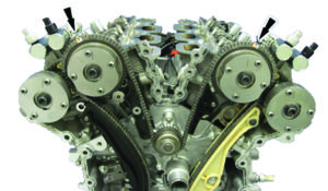
Let’s start with the obvious differences between the Gen 1A and Gen 1B right side cylinder head camshafts, and pictures are the best way to do that. The lines in the front and rear view portray the clock angle of the first lobe that you come to. (Photos 18 and 19, page 44)
The Gen 1A right side cylinder head intake and exhaust camshafts have the same casting number so you’ll need additional visual identification to tell them apart. Some people swear by the ground ring, but I wouldn’t suggest that you bet the farm on that.
The one true ID is by the QR code on the camshaft barrel that, fortunately, has the OE part number on it. The left side head is not as complex of an ID, however, the QR code is still your definitive guide (Photo 20, page 47).
Last but not least there are floating seals that run in two grooves in the front camshaft journal and keep the feed oil contained in a specific band in the housing bore. The floating seals are split on a long taper that mate once in the groove and bore (Photo 21, page 44).
Timing
I am not going to do a step by step instructions on installing the timing, because I found a good number of installation videos online suitable for just about every level of time and expertise. I did find one that was 45 minutes long and goes into every possible detail regarding struggle, tools, parts and pit falls that you could ever encounter.
So let’s start at the beginning – you will want to install the top guides prior to anything else because there are bolts that get under the cam-to-cam gear/phaser and chain assemblies. The camshafts need to be held in place by tooling/fixtures to install the C-C assemblies. And there is a chain tensioner for these assemblies that has a stationary bottom shoe and a top shoe that is oil pressure-activated. The tensioner has a plastic retainer that must be removed. However, if you do not depress the plunger to release the internal snap ring the tensioner will never activate. If you activate the tensioner prematurely there is no way to get it locked again. There is a special tool made for that circumstance and also used on the service side if required. The bolts for the upper timing gears/phasers use a TP55 Torx bit which is unlikely to be in your tool box.
According to Engine Builder’s sister publication UnderHood Service, Since the 3.5L EcoBoost is turbocharged, the oil is under extreme stress. If the driver pushes it past the recommended oil change interval, the first item to show the abuse is usually the timing chain. Worn-out oil can damage the chain, guides and tensioner. When the chain is worn and stretched, the PCM detects the changes in camshaft position and sets code P0016 for crankshaft/camshaft correlation. Check out Ford’s TSB 14-0194 for more information.
Warranty Pro-Action:
Well, if your head is not spinning yet strap in – we still have some fun things to go over. This may be somewhat of a new area for this type of article, however, if you know the pitfalls, understand the proliferation, and have conquered the machining challenges, do any of your warranty people have any experience with helping your customers avoid premature failures or diagnose struggles that they are having? Well, as best we can, that is exactly what this section is meant to do – help your warranty assistance transition into warranty Pro-Action
The first matter to address is the OE recommended ten thousand-mile oil change intervals. If there is a reported weak link (no pun intended) it is the timing chain. However, after speaking to a number of technicians, checking the condition of the core being returned, and analyzing what I read in blogs, there is a single consensus about premature failure for this engine and that is poor oil maintenance. Timing chain breakage, and turbo seals were the most frequently mentioned failures. So my question is, could changing oil “on the fives” be a life insurance policy that could pay monumental dividends in your customer’s truck engine life?
Before performing any diagnosis on any GTDI engine, visually inspect all air intake and vacuum hose connections. The smallest air leak can cause driveability issues, misfires and set DTCs. During your visual inspection, you might notice oil residue around the turbos’ cast iron housing. It will almost appear that the turbine housing is sweating oil. This is normal due to the PCV system. However, oil leaking, draining or puddling is not normal.
Turbocharger output must be regulated to prevent excessive intake pressure, or overboost. The powertrain control module (PCM) controls exhaust flow to the turbos using a turbocharger-mounted wastegate, which directs exhaust flow around the turbocharger when needed. The wastegate is opened by a diaphragm operated by engine vacuum. The PCM uses an intake manifold-mounted MAP sensor to monitor boost pressure. Then, using a wastegate-regulating valve solenoid, it commands the diaphragm to move a poppet-style valve that redirects exhaust flow around the turbo. The valve is held in the closed position by spring pressure. A threaded rod connects the diaphragm to the valve, and although the rod has an adjusting nut, it’s not adjustable. The rod comes from the factory with a painted cage over the adjusting nut. If the cage is missing, or if the paint is disturbed, someone has tried to adjust it, and the entire turbo must be replaced, since the wastegate and rod cannot be serviced separately (Photo page 47).
GTDI turbochargers are mounted directly to the exhaust manifolds allowing them to reach up to 170,000 RPM very rapidly. This, along with the low-inertia rotors that drive the turbine, allows for quick turbo reaction and virtually no turbo lag. However, this also makes them vulnerable to damage from loose carbon pieces. DO NOT use top cylinder cleaner on an EcoBoost engine. It will create excess heat and the breaking away of rough carbon chunks will damage the turbos. Ford is apparently working on an approved induction cleaning system, but my latest searches and inquiries have not uncovered a solution yet.
There’s a screen located in the turbocharger oil supply line. Always replace it when replacing a turbo that has failed, and if you remove the air inlet or outlet hose from the turbo, cover the openings! The smallest piece of debris can destroy a turbo.
Here are some tips for diagnosing turbocharger noise concerns. An air turbulence sound or a “whoosh!” noise during throttle tip-in could be caused by turbocharger imbalance, meaning that both turbos are not operating evenly in relation to each other. Check the paint on the wastegate rods. Other noise concerns include a whistling sound or a hissing sound. A whistle is usually caused by a leak in the low-pressure side of the turbo; a hiss is normally a high-pressure leak, past the turbo. During quick throttle releases, intake air from the high-pressure turbocharger outlet is redirected to the low-pressure turbocharger inlet by the turbocharger bypass valve (TCBV). This recirculating of airflow prevents loud air sounds that are caused by the backup of intake air through the turbocharger. When the TCBV is stuck closed, the air sound during a quick deceleration can be pretty loud, and will often generate a customer complaint.
Black smoke during initial start-up, and especially during the first cold acceleration event, is considered normal. This is due to the dual-pulse injection strategy used during a cold-start event. During cold start-up the injectors deliver a small spray on the downstroke of the intake cycle, then another spray at the top of the cycle. The shape of the piston forces the fuel towards the spark plug, allowing a good cold-start mixture without creating a rich condition. This tends to cause some black puffs from the tailpipe. If the fuel trims don’t indicate a rich condition, it’s normal.
That tap, tap you hear coming from an idling EcoBoost engine is not a valve train noise but normal operation of the high-pressure pump on the left side cylinder head valve cover. A rubber noise cover is fitted over the pump to help suppress the noise. If someone forgets to install this suppressor it will sound 100% as if there is a valve train noise. It might be a bit disappointing to remove and engine or cylinder head for a missing sound cover.
That same cam driven tappet needs to be replaced upon engine or cylinder head replacement. Also there has been many a technician who has forgotten to install it completely, it’s an easy thing to miss. The engine will idle fine without it, but will develop a miss immediately upon acceleration.
Ford does not recommend back probing the fuel injector harness plug while the engine is running, as this can damage the PCM. If you have an inoperative injector, check both wires from the injector to the PCM for continuity. Remember, it takes 65V to fire these boys.
One concern that’s becoming a problem with all GTDI engines is excessive carbon buildup on the back side of the intake valves. This causes hard-to-diagnose misfires, especially when the engine is cold, and can also create a rough, rolling idle. Oh, and do we remember the problem with carbon chunks hitting the tubo fins while spinning at 170,000 RPM? Another contributor to this issue is the PCV system. Besides the normal crankcase vapors that enter the intake from the PCV system, these vapors can also enter the intake from the turbocharger. A check valve in the PCV vacuum hose diverts crankcase vapors to the turbocharger’s low-pressure hose under boost conditions. This prevents the backflow of pressurized intake air through the PCV valve and into the crankcase. The only sure way to diagnose excessive carbon buildup is to look at the valves with a borescope. So if you’re diagnosing a phantom misfire on a GTDI engine, especially if it’s worse cold and after eliminating the usual suspects, break out the borescope.
3.5L Second Generation
Okay, so maybe there is some bonus coverage of the next-generation 3.5L EcoBoost after all. The newer version of the powerful V6 started being produced last year for the 2017 Ford GT. It produces 647 hp paired with a seven-speed semiautomatic transmission. This engine theoretically replaces the 5.4L supercharged modular V8 from the last generation Ford GT.
The 2017 Ford F-150 SVT Raptor is powered by another all-new 3.5L twin-turbocharged EcoBoost V6 that produces 450 horsepower, up from the previous 6.2L V8’s 411.
The same second-generation 3.5L V6 replaced the first-generation engine in the 2017 F-150 line-up. It will be standard on the F-150 Limited and remain an optional upgrade for many other trim levels. From what I understand it appears that both first and second generation engines are available in 2017 vehicles. Paired with the second-generation 3.5 L EcoBoost V6 is the new 10R80 10-speed automatic transmission. This new transmission is mandatory with all new second-generation 3.5 L V6 EcoBoost F-150s, with the new transmission being restricted to this engine solely for the 2017 model year.
There are close to half a million 3.5L EcoBoost engines on the road today and many of them are out of warranty.
It’s a pretty incredible engine and should provide plenty of opportunity for maintenance and upgrade work for years to come.
Roy Berndt has decades of machine shop and engine building experience. He is the Program Manager for LKQ Remanufacturing in Springfield, MO.