Engine bearing inspection is a great way to get a visual indication of what is going on inside the engine under operating conditions. Upon teardown, the bearings will often have “tell-tale” signs of problems that have occurred and need to be addressed. However, the distress noticed in the bearing is often misunderstood and referred to as a bearing failure.
Bearing failure is a subject that needs to be addressed because, technically, the engine bearings did not fail. If proper attention and detail had been given during the assembly, there should not be a bearing failure.
The proper term for bearing failure should actually be bearing distress or fatigue. If an engine was assembled properly, the engine bearings should be in good shape during the tear down. There should be “normal” signs of wear, but if there are signs of distress or fatigue, these problems need to be recognized in order to prevent an engine failure.
Identifying bearing distress is very important because there are several factors that will only cause the bearing to fatigue. Most of the factors that cause bearing distress can be prevented during the assembly process. Other factors are caused by improper lubrication, which has several different factors that need to be addressed also. We will cover the relationship between bearing fatigue and issues of the lubrication system so a correct engine assembly can be achieved for the operating environment the engine will be exposed to. There are seven major causes of bearing distress that need to be recognized for proper engine assembly and operation.
An engine bearing has a tremendous responsibility, therefore, it has to be comprised of materials that are strong enough for load, wear and cavitation resistance, but soft enough for conformability and embed ability. When assembling an engine, you have to consider the proper bearing material for the application or bearing fatigue and distress can occur.
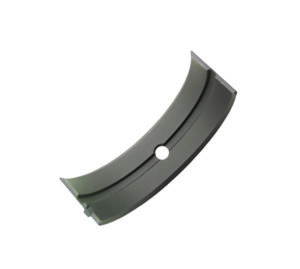
To keep things simple, there are two different types of bearing structures that are commonly used – bi-metal and tri-metal bearings. Bi-metal bearings have a bottom layer of steel, which supports the bearing structure and provides rigidity. The top layer is the bearing lining, which is composed of aluminum with an addition of other alloys such as tin, copper, silicon and nickel. The top layer is usually thick, which allows for small imperfections of geometry, surface finish and misalignment. Bi-metal bearings are typically very forgiving and are great for light load and stock rebuild applications.
The tri-metal bearing has a steel backing with an intermediate layer of copper-tin-lead alloy. The overlay is a lead base known as babbit that is applied very thin to the intermediate layer. The overlay offers low resistance, conformability and embed ability. This bearing is more expensive and used for higher power output engines where there is more load demand on the bearings.
Once the proper bearing is chosen for the application, extreme detail should be given to the assembly. Most professional engine builders follow a systematic approach to properly check and gauge all components and properly clean the components before final assembly. If you’re one of those, congratulations. If not, well, it’s a good thing you’re reading this article!
Close attention should be given to all engine components during the “mock-up” phase of the engine build. Start with the geometry of the engine components. Make sure that all of the main caps of the block are aligned. The crankshaft imposes heavy loads on the main bearings and, over a period of time, the heating and cooling cycles of the main bearing caps can cause distortion. Check the main bearing alignment, and if needed, have the block align bored.
This step applies to the rod bearing caps as well. The rod journals of the connecting rods need to be properly sized, not only for alignment, but also for proper bearing crush. Having too little or not enough bearing crush will result in heavy wear or spotted wear of the bearings.
The crankshaft also needs to be checked for straightness and proper size. Bent crankshafts and out of round journals cause accelerated wear and fatigue to the rod and main bearings.
Having the proper finish on the crankshaft journals can be just as important. These elements will cause heavy wear along with localized wear on the bearings that can often take away the bearing overlay or produce very distinct shiny spots on the bearing surface. This is often found on the rod bearing surface that rides the crankshaft rod journal filet. The edges of the rod bearing will be shiny and worn because of the needed clearance where the rod bearing is contacting the filet.
There are chamfered bearings for high horsepower crankshafts that have the larger radial rod journal filets.
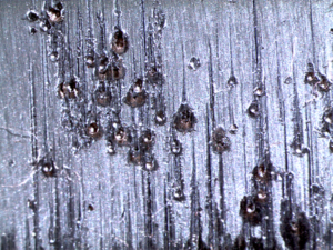
Remaining abrasives or improper cleaning tends to also be a major cause of bearing fatigue. There are several ways to clean engine components, but there seems to be some misconceptions about which is the right one. However, if you talk to many professional engine builders you will find there is only one way to clean and that is the “old fashioned” way – elbow grease. Engine components need to be hot tanked with all of the oil and coolant passages exposed. This lets the cleaning solution penetrate these passages to free up the muck and grime. Often, builders will then remove the components and use some sort of steam cleaning along with properly sized bristle brushes to clean the passages out.
Proper cleaning takes a lot of time and requires attention to detail because the trapped particles will almost certainly come loose and find their way into the oiling system where they will pass the bearings until being trapped by the oil filter.
Experts caution against the use or any form of glass beads or sand because, while they will clean, they’ll simply leavebtoo much residue, which is nearly impossible to remove entirely. Also, abrasives or dirt found in the bearing material may be filtration related, especially if the engine is used in dirt track applications.
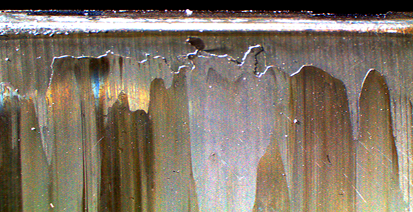
In addition, you’ll want to make sure you’re choosing the proper oil viscosity for the application since this can be crucial to preventing bearing fatigue. Oil viscosity selection is often related to bearing clearance of the engine. Professional oil manufacturers will often recommend oil based on the engine application and bearing clearance. Using the wrong oil and insufficient oil pressure will cause unstable oil film on the bearings and starve the surface of the needed protection. This can often be recognized by signs of blackening of the bearing from overheating or missing or melted overlay of the bearing surface.
Erosion damage can also be seen on the overlay due to sharp changes in oil pressure. If oil pressure drops at high engine rpm, bubbles can form in the oil from cavitation. The hot surface of the bearing causes these bubbles to boil off or evaporate – when the pressure rises again, the bubbles leave a scoring on the surface of the overlay, causing erosion. Insufficient oil supply will cause the overlay surface to deteriorate rapidly. Excessive blow-by, oil change interval, coolant and fuel will contaminate the oil.
Although the engine’s operqting environment such as dirt, sand, salt, extreme heat or cold can have an effect on all of the internal components, how the engine performs is very crucial to bearing life. Underlying problems such as detonation and pre-ignition can play a vital role in bearing life. In high performance applications, the internal problems may not be audible.
Detonation occurs after the cylinder has fired and the piston is traveling down the bore. A portion of the end gases ignite and cause major loading on the rod bearing along with harmful effects to the piston crown. The same thing can happen during pre-ignition, which results from the air/fuel mixture igniting before the spark plug has fired.
Cam bearing distress needs to be mentioned also. For years, cam bearings were made with a lining of babbitt. Babbitt is kind of a soft, slippery material made up of lead and tin and is very similar to solder. The babbitt surface layer of the bearing was very forgiving and could survive abuse from foreign particles, misalignment and minimal oil at the start-up.
Because modern engines produce higher operating temperatures and valvetrain loads, babbitt can’t survive under these conditions due to its low strength. Babbitt has now been replaced with an alloy of aluminum, making it harder. The stronger alloy can endure the higher valvetrain loads along with the heat, but in return is not as forgiving. It is now less compatible with dirt, misalignment and minimal oil at start-up.
Clearance is very important with the use of modern alloy bearings. The softer bearing material would wear-in rather rapidly where the harder alloy will not. Minimum clearance should be about .002˝ for stock engines and .003˝ for high performance.
Bearing coatings have become very popular for all applications. In simple terms, the coating is a polymer filled with lubricants such as moly and graphite, which help reduce metal-to-metal contact and aid in start-up. The coating has to be taken into account for additional clearance that may be needed. Bearings that are coated offer high-seizure resistance, low friction and embedability.
However, coatings are often sacrificial layers and can wear fast under high load conditions creating more metal-to-metal contact. Once the coating is gone, the clearance is increased by the value of the coating thickness. Still, as long as the engine performs well and all clearances and alignments are good, the coating should last as long as the lubricating system performs with the right viscosity of oil.