 Valve springs play an essential role in controlling the breathing in internal combustion engines. The valves are mechanically opened by a camshaft, with the help of the valve lifters or tappets, and closed by the valve springs. But valve springs perform one of the most the critical functions: lifting the weight of the valve.
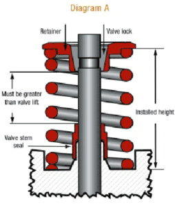
Valve springs apply force against the retainer to push the valve closed. The pressure exerted by the spring increases when the rocker arm or the cam follower moves and pushes the valve open. This force pushes the valve shut again as the rocker arm or follower rotates away from the valve, and it maintains valve lash.
The valve springs must apply a certain amount of spring pressure to maintain correct valve operation at normal engine speeds. When the valves have fully closed, the pressure against the valve in many stock engines is usually between 70 to 90 psi. When the valves are open by the valvetrain, the pressure on the springs may be 200 psi or more. Racing and performance engines need stiffer valve springs to reach higher rpm without floating the valves and can see closed spring pressures of about 200 to 300 psi, and open loads of 1,000 pounds or more.
 Just looking at a valve spring won’t be enough to determine if it’s bad. The only way to inspect valve springs is to test each one individually on a valve spring test stand. The test stand gauge shows much force it takes to compress the spring a certain distance. If a spring fails to meet the pressure specification you want, the spring should be replaced.
Valve springs should also be replaced if they are out-of-square. Place the springs against a 90-degree square to see if the coils have deformed. Also look for signs of damage (such as nicks, scratches or corrosion), for coil binding (look for shiny spots between coils that make contact), or worn areas on the ends of the springs. Replace the valve springs if they have any visible defects.
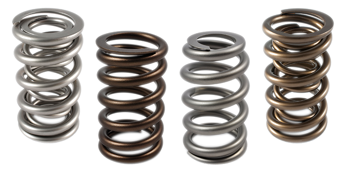
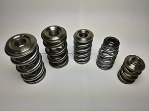
Springs come in several styles, shapes, and sizes such as singles, doubles or even triples. Springs are chosen carefully for just the right pressure for the lifter to follow the cam lobe. Engine builders look for the lightest spring to control the valve to keep it closed and not allow it to chatter because high spring pressure requires more power to operate. Using more spring pressure will not produce more power if a single spring can control the valve. But if the valve chatters, cylinder pressure will be lost. Valve chatter or valve bounce is when the valve bounces on the seat as it closes. Not enough spring pressure or valves closing too aggressively can cause chatter even when the lifter follows the cam lobe just fine.
 Seat pressures used with flat-tappet camshafts are usually around 120 psi to 140 psi. However, by using particular run-in procedures with expensive tool steel flat tappets and camshafts, some engine builders can use 200 psi seat pressures and beyond.
Spring selection has been influenced by new wire shapes and configurations today. Coil spring wire was round, but now some springs use ovate (oval-shaped) wire. With ovate wire, more spring can be used in a given amount of space. This means at the same installed height, an ovate wire can handle more lift than a round-wire spring before fully closing.
New materials and configurations have been developed in the last 10 years or so to allow smaller springs to work with larger cams. Today’s double springs can often do the work that triples did in the past. One engine builder we know tested the theory of removing the inner on a triple and didn’t lose anything.
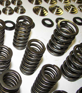
Some engine builders prefer a dual spring because if one spring breaks, the other spring acts as insurance to prevent valve drop long enough to shut down and avoid a colossal failure. However, singe beehive springs are less likely to fail than conventional springs because the configuration reduces harmful spring harmonics, and they can add more power.
Coil bind needs to be avoided at all costs when installing new springs. If the coils binds at or before full lift, a bent pushrod may result in the best case, but a broken spring, a dropped valve, or worse could also happen.
When installed at the correct height to produce the required seat and open pressures for the engine, the spring needs to have a safety margin before coil bind occurs. To check if the spring has sufficient coil bind clearance use the valve spring installed height on the seat, minus cam lobe lift, multiplied by rocker arm ratio, plus valve lash, minus the safety margin. This should be equal to the remaining open spring length, and equal to or greater than the spring manufacturer’s published coil bind height.
How much safety margin is needed? It used to be typically at about .060˝ or more. This is still acceptable for mild performance use, but in some cases now, .060˝ is the maximum. One valvetrain manufacturer notes that high-speed video and testing shows adjacent coils contact when the valvetrain limiting speed is reached. The manufacturer said that new springs are meant to operate near coil bind and use the coil-to-coil interaction for dampening at or near max lift. The interaction between the coils is one of the best ways to dampen spring surge, but the valve spring must be designed correctly to use this interaction effectively and safely.
Depending on the application, the spring and cam lobe design and the engine builder’s preferences, coil bind safety margins can vary from as low as .015˝ to as high as .120˝, with tighter numbers for stiffer valvetrains. In many valvetrains, more than .150˝ can cause spring surge, which can significantly lower the amount of spring load needed to close the valve.
Choosing valve springs must also factor in the gear that retains the spring on the valve stem – the retainers and locks. The retainer diameter must fit the spring. For dual or triple springs, the steps must be in the correct location to match each spring. The retainer fit should be snug but not excessively tight. Some engine builders prefer at least .010˝ interference fit, while others like .005˝ interference fit. Too little clearance puts stress on the spring wire and will likely lead to failure. Without enough clearance between the coils, stress is added at the spring tip that can lead to a failure. There will be more wear between the spring and retainer if the retainer is too loose, according to one valvetrain manufacturer. This applies to each spring comprising multiple spring assemblies.
It’s important to use the manufacturer’s recommendations when matching the retainer and springs. It is critical not only for the outer spring but also because the retainer step is used to locate the inner spring on dual- and triple-spring applications.
The valve lock angle must be compatible with the retainer. Typically, valve locks had an angle of seven degrees of incidence. Some manufacturers have developed locks with a steeper angle. The bigger angle produces more contact area, spreading the load over more surface area. A configuration of ten degrees has, for the most part, become the industry standard in many performance applications. However, that doesn’t mean seven-degree locks are dead. Some engine builders say a seven-degree lock puts more clamping force on the valve.
While the retainer step locates the retainer to set the correct installed height, it doesn’t keep the retainer in place. The clamping force of the spring pressure holds the retainer in place, and the clamping force increases when pressure increases. An eight-degree lock has almost as much surface area as a 10 with the clamping force of a seven.
Different valve stem sizes will require locks to match. Most valves are machined with square keeper grooves for domestic applications. However, imports, many late-model domestics, motorcycles and custom valves often use a radiused beadlock groove that is less likely to develop stress cracks. There are no sharp edges on a radiused groove and it has greater contact depth. However, the production process is more costly, so it may not be necessary for every application.
Valve springs and other valvetrain parts should be chosen to work together as well as complement the cylinder head’s characteristics. Be careful to select parts that work in concert with each other to reliably produce the desired power output for the engine application. Everything affects everything else.