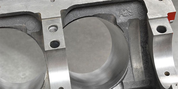

Sleeving an engine block is done for two primary reasons. The first is to repair a cracked or otherwise damaged cylinder to save the block. The second is increasing displacement by allowing for a larger bore size. In either case, the sleeving process must be performed carefully to ensure satisfactory results. Careful measurements are required to install the sleeve in the correct location and with the correct it. There are also two basic types of sleeve – dry sleeves and wet sleeves – which penetrate the water jacket.
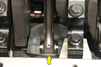
Before we get into the details of sleeve selection, it is also important to consider the length of the sleeve, particularly when building a stroker application. Many builders spec a longer stroke engine that pulls the bottom of the piston partially out of the bore at BDC (bottom dead center). There are ways to make this work, but when the piston’s gauge point is uncovered, the piston rocks too far and the skirts are instantly damaged. To counter this, you must spec a combination of rod length, half the stroke length and sleeve length that ensures the piston’s gauge point will remain properly captured throughout BDC.
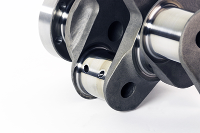
Before you spec a stroker combination you must measure the existing cylinder height and determine if it will fit properly with your sleeve and stroker installation. The sleeve rests on a bored ledge at the bottom, which effectively shortens the available cylinder length. If you cannot achieve the proper dimensional stack you will not be able to stroke the engine to your desired amount. You must calculate half the stroke length, rod and gauge point to see if it will accommodate your needs. To ensure safe operation, the gauge point must be at least 0.250˝ or more above the bottom of the sleeve so it will completely capture the piston and prevent rocking. The gauge point is typically 1˝ below the centerline of the wrist pin, so add that to your dimension stack when figuring sleeve height.
You can model this on paper using the following dimensions:
Rod Length
½ Stroke Length
Gauge Point Dimension
The total of all these must be less than the length of your sleeve by 0.250˝ safety margin.
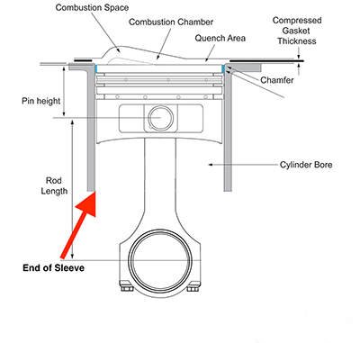
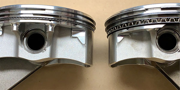
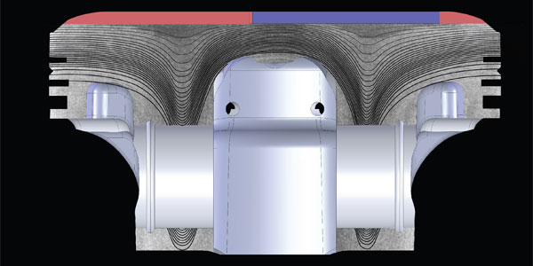
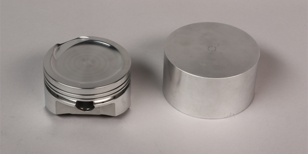
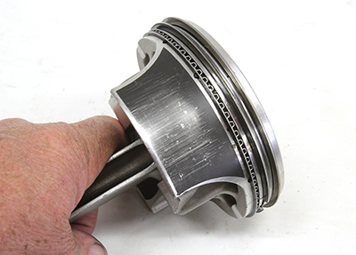
The location of the gauge point is the critical part because that is where the piston will rock if it moves lower than the bottom of the sleeve. The gauge point (CH or checking height) is the lower stability point on the piston skirt. It works in conjunction with the ring pack to keep the piston square in the bore. If the piston rocks, the skirts dig into the sleeve and are instantly ruined. Sleeving can work against you in these cases because it almost always shortens the cylinder length by the amount necessary for the mounting step at the bottom of the bore. If you cannot achieve the proper dimensional stack, you will not be able to stroke the engine to your desired spec. Some sleeves use a smaller step that allow the sleeve to extend past the step. Your experienced machinist will know what to use.
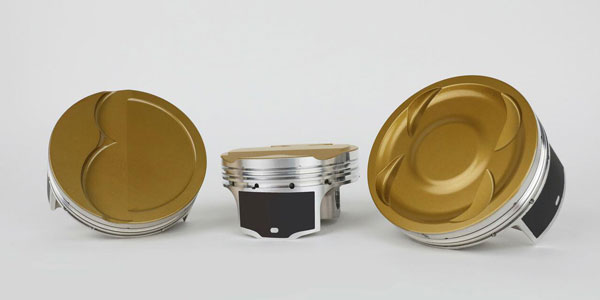
According to Alan Stevenson at JE Pistons, “Our standard for total piston height is CH +1.00”. The gauge point varies by forging design: full round forgings have different cam shapes than slipper-style (what we call FSR or Forged Side Relief) forgings. Typical gauge point for a full round is .500˝ above the bottom of the skirt and .275˝ up from the bottom on an FSR.”
The formula for determining if the gauge point is captured on a full round piston is:
Sleeve length – (CH + .750˝) – stroke.
The .750˝ number is an “aim to” that is arrived at this way: Overall length is CH + 1˝, and the gauge point is .500˝ above the bottom of the skirt, so it is expressed as CH + .500˝ + .250˝ (the safety margin) or CH + .750˝.
So, if we look at a typical 383 SBC (3.750˝ stroke, 6˝ rod, 1.125˝ CH) that has, say, 5.7˝ long sleeves:
5.700˝ – (1.125˝ + .750˝) – 3.750˝ = 0.075˝. This means we’re .075˝ to the good. Any positive number using this formula means the gauge point will be captured, plus have .250˝ safety margin below the gauge point, plus the difference of the formula. In this case, the gauge point would be captured by .250˝ + .075˝ = .325˝.
For an FSR-style forging, the .750˝ number changes to 0.975˝ since the gauge point is only .275˝ above the bottom of the skirt and we still need the gauge point captured by .250˝. So with the same example engine:
5.700˝ – (1.125˝ + .975˝) – 3.750˝ = -.150˝. This means we’re .150˝ short of the .250˝ safety margin, or conversely that the gauge point is only captured by .100˝.
Stevenson added, “This is also where the type of cam shape on the skirts goes from important to critical. Certain cam shapes taper outward below the gauge point, others go straight down from the gauge point, and some “tuck” underneath the gauge point. If part of the skirt protrudes at BDC, the first two will wear very visibly and very quickly, while the third will handle the protrusion with much less drama.”
“We recommend beginning with these basic calculations and then having a conversation with your piston manufacturer to decide on the right cam shape based on the severity of the protrusion.”
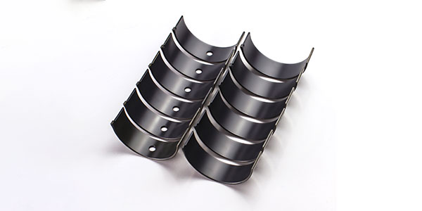
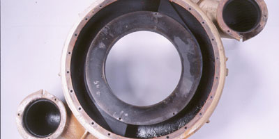
Some builders have been known to sleeve a block just for repairs while others have sleeved the entire block to gain strength and ensure uniformity. Dry sleeves are the most commonly used, but wet sleeves have gained popularity, especially in newer engines which already have wet liners. Two materials are used; grey cast iron and ductile iron. Either is suitable for most applications.
Grey iron is best used in an environment which is highly controlled. The installer or engine builder will be satisfied using the grey cast iron in an iron block with very stable wall thickness. The wall thickness is key because it will hold the sleeve in a stable area, ensuring good ring seal.
Ductile iron is twice as hard and strong as the grey iron and is appropriate for applications that are far less predictable, such as in very thin-wall iron block motors or most aftermarket aluminum blocks. In aluminum blocks, where wall thickness is a major consideration, an engine builder will want to use ductile iron because the ductile material will reinforce the lightweight alloy blocks. Ductile iron can be warped under a heavy load, but it will return to its beginning origin because it has tremendous memory. The material can adapt to the movement of the piston or aluminum block and bring it back to round.
If you are installing dry sleeves in a block to increase displacement, you can remove only so much metal before you run out of block to support the larger cylinder sleeves. One way to overcome this limit is to do a wet sleeve conversion. The existing cylinders are machined away, and wet sleeves are installed in their place. Installation involves extensive modifications to the block and requires precise CNC machining so it can accept wet sleeves, but the results are worth it. Because the coolant is in direct contact with the outside of the sleeve, wet sleeves can typically handle much higher horsepower and heat loads. Consequently, you gain increased strength and reliability as well as more displacement. Wet sleeve conversion kits are available for certain late-model import engines as well as domestic V8s.
Installing sleeves is best left to your professional machine shop as they do it all the time. But it is up to you to calculate the sleeve depth and how it will accommodate your stroker application. A piston that drops too far out of the bore near the gauge point amounts to moving parts hitting each other in a running engine – and that is never a good thing.
This article was sponsored by K1 Technologies. For more information, visit www.K1Technologies.com